Cover body for air bag apparatus

a technology for airbags and apparatuses, applied in the direction of vehicular safety arrangements, pedestrian/occupant safety arrangements, other domestic objects, etc., can solve the problems of increased cost, unintended tearing, instrument panel itself receiving the impact of airbags, etc., and achieves superior safety and reliability, durability and appearance.

Active Publication Date: 2006-08-22
NIHON PLAST CO LTD
View PDF24 Cites 39 Cited by
  • Summary
  • Abstract
  • Description
  • Claims
  • Application Information

AI Technical Summary

Benefits of technology

[0014]It is therefore an object of the present invention to provide a cover body for an air bag apparatus which is superior in safety and reliability, also durability and appearance, across a wide range of temperatures.
[0015]It is another obje...

Problems solved by technology

During inflation of the air bag, due to these portions of the instrument panel not being supported, the instrument panel itself receives the impact of the air bag.
This is a factor which increases cost.
This leads to a possibility of unintended tearing, suc...

Method used


Image

  • Cover body for air bag apparatus
  • Cover body for air bag apparatus
  • Cover body for air bag apparatus

Examples


experiment i

INFLATION EXPERIMENT I

[0084]Three instrument panels, i.e., cover bodies, with integrated air bag apparatuses were prepared according to the first embodiment of the present invention as shown in FIGS. 1 through 4 to serve as EXAMPLE I, EXAMPLE II, and EXAMPLE III. Each of the instrument panels was made from polypropylene and each of the backing members from thermoplastic polyolefin elastomer, having the physical properties shown in the table below. Instrument panels with integrated air bag apparatuses were prepared as examples of the related art for COMPARATIVE EXAMPLES I through VIII. The inflation experiment was performed at a room temperature of 23° C. Results from observation of the experiment are also presented in the table.

[0085]

Instrument panel (PP)Backing member (TPO)flexualflexualelastictensileelastictensilemodulusstrengthIzodelongationmodulusstrengthIzodelongationMPaMPakJ / m2%MPaMPakJ / m2%Results of experimentEXAMPLE I2,15029.56.43125013570NBSmooth inflation with infla-tion s...

experiment ii

INFLATION EXPERIMENT II

[0086]An instrument panel having an integrated air bag apparatus is constructed to serve as COMPARATIVE EXAMPLE IX representative of the related art, a hinge size thereof being of comparable largeness to EXAMPLE I, however, other than a shape in cross-section thereof being a bent shape with no flat portion, a hinge thereof is the same that of EXAMPLE I, as shown in FIG. 26A. Inflation of COMPARATIVE EXAMPLE IX was observed during an inflation experiment performed at a low temperature of minus 30° C.

[0087]Results of the inflation experiment show that although the air bag of COMPARATIVE EXAMPLE IX inflated into a predetermined shape, stress evidenced by white blush marks at many locations occurred in the attachment-side portion of the hinge, and a crack designated by X formed in proximity to the tear seam. Partial breaking occurred in the instrument panel where the crack had formed, shown in FIG. 26B.

[0088]In contrast, with EXAMPLE IV which used the same arrange...


PUM

PropertyMeasurementUnit
Fractionaaaaaaaaaa
Pressureaaaaaaaaaa
Pressureaaaaaaaaaa

Abstract

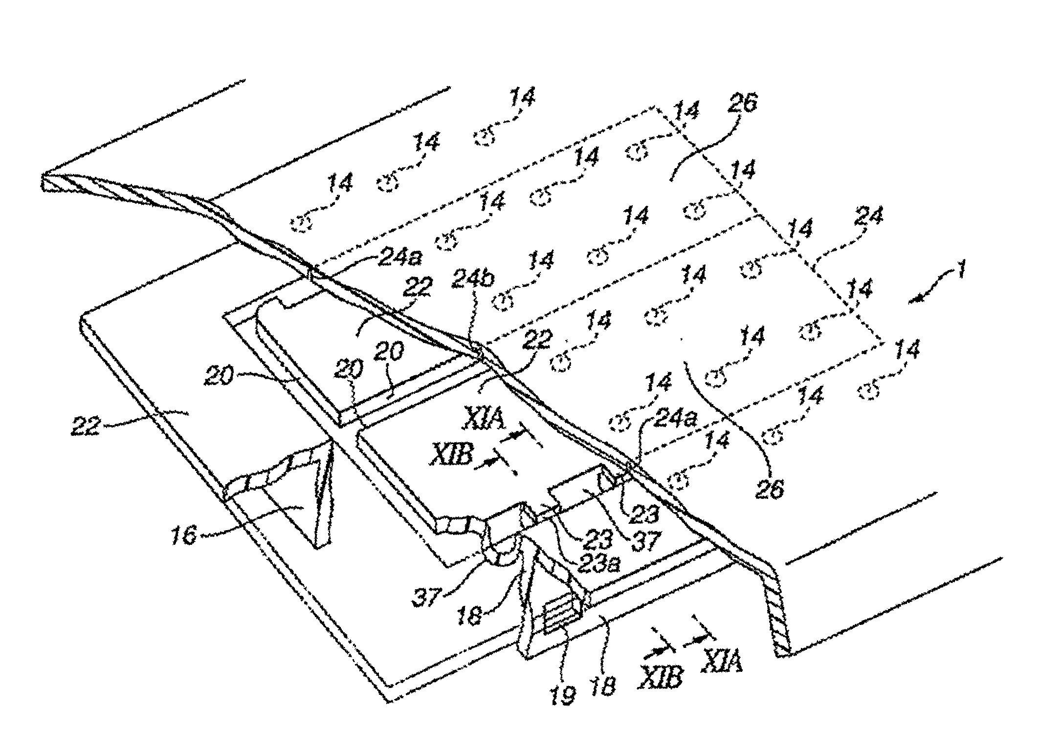
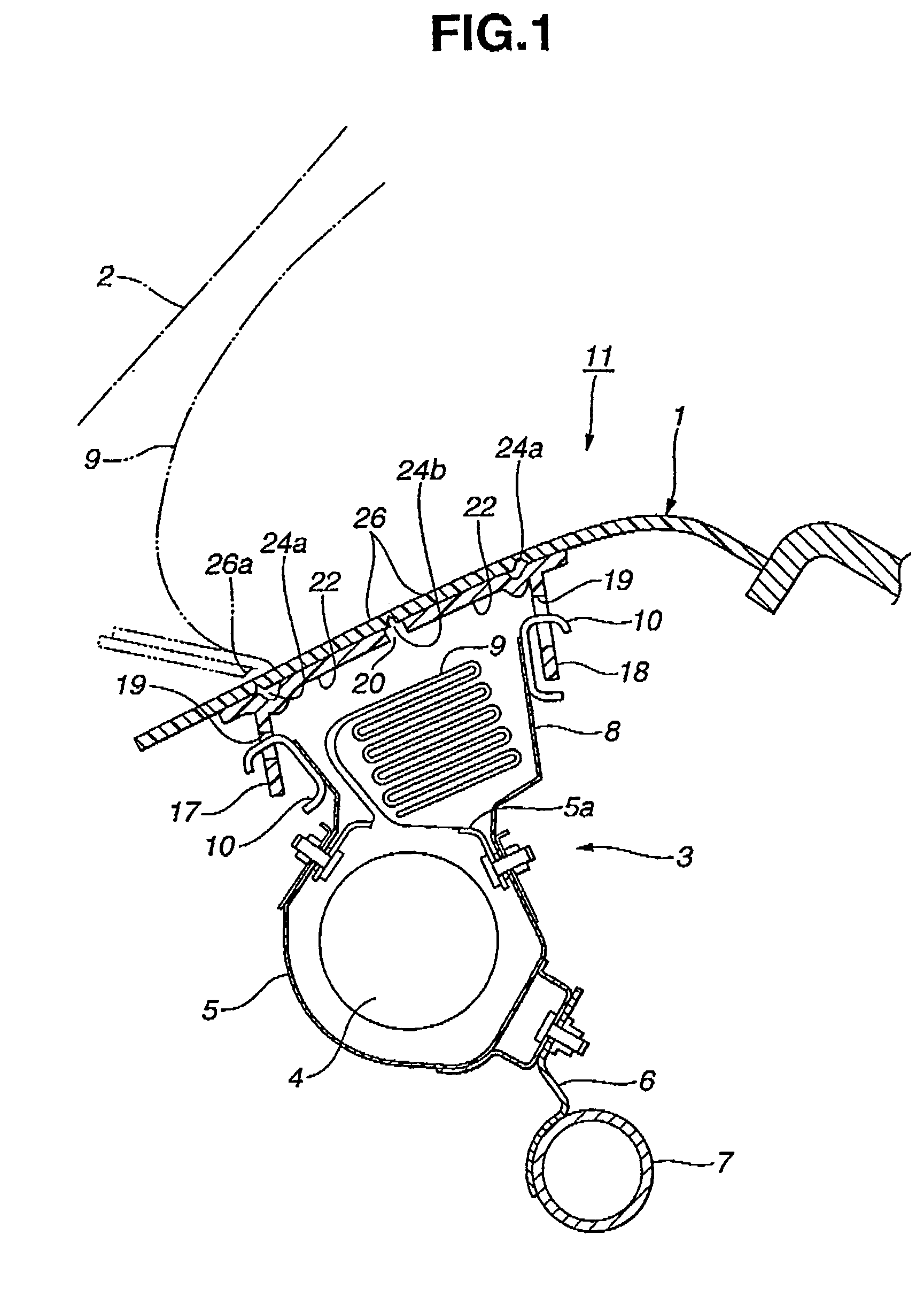
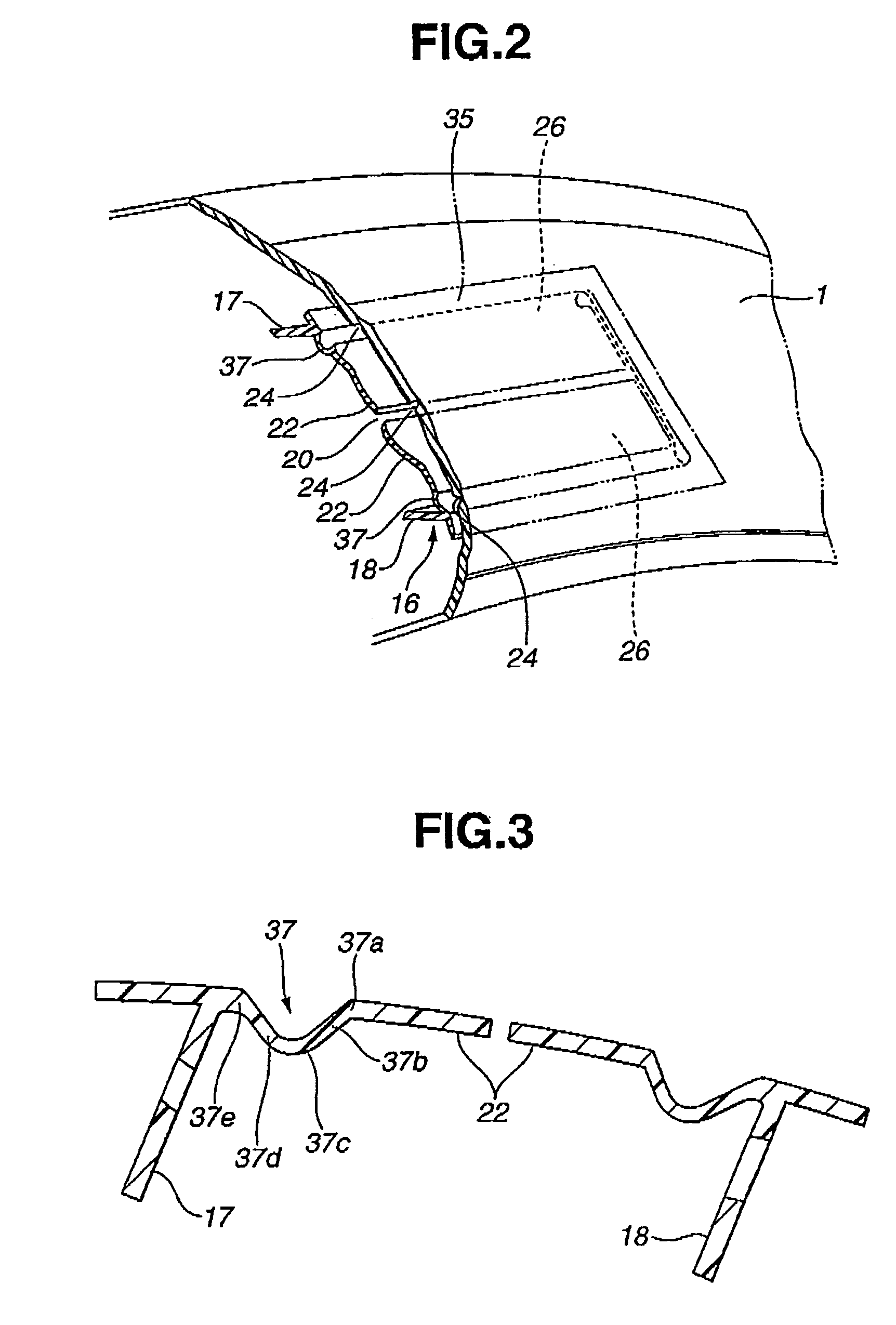
A cover body of a vehicle air bag apparatus, being comprised of a covering portion which is formed integrally with an interior panel body and which has a door portion defined by a tear seam formed in a back of the interior panel body, and, a backing portion joined to a back of the covering portion. The covering portion is made of polyolefin resin having a flexual elastic modulus of from 1500 to 3500 MPa, a tensile strength of from 17 to 40 MPa, an Izod impact strength of from 3.0 to 15.0 kJ/m2, and an elongation of 400% or less. The backing portion is made of thermoplastic olefin which is softer and has a greater elongation. The backing portion is comprised of a reinforcing portion at a back of the door portion, a surrounding base at the back of the covering portion, and a hinge portion joining the reinforcing portion and the surrounding base.

Description

BACKGROUND OF THE INVENTION[0001]The present invention relates to a cover body for an air bag apparatus which is integrally formed with an internal panel of a vehicle. This invention is applicable particularly, but not exclusively, to a cover body for an air bag apparatus to be used for a front passenger seat, the cover body being formed integrally with an instrument panel.[0002]Instrument panels located below the front window of a vehicle have been designed as instrument panels with hidden seamlines, which have an integrated air bag apparatus comprising an air bag and an inflator stored inside the instrument panel. Within the instrument panel, a lower portion of the air bag apparatus is fixed to a steering member disposed along the direction of the width of a vehicle, and an upper portion thereof is attached to a pair of attaching members consisting of a back and front member which are formed integrally with a rear of an instrument panel.[0003]Japanese Patent Provisional Publicatio...

Claims


Application Information

Patent Timeline
IPC IPC(8): B60R21/20B32B27/32B60R21/205B60R21/215B60R21/2165
CPCB32B27/32B60R21/2165B60R21/205B29C65/02B29C65/06B29C65/08B29C66/21B29L2031/3038B29C66/542B60R2021/21537B29C66/53461B29C65/00B29C66/30221B29C66/30223B29C66/532B29C66/54B32B27/08B32B2605/00
Inventor NISHIJIMA, KAZUYOSHIYAMADA, SHUJITONOOKA, MASAMIKITAZAWA, SATOSHISUWAMA, TAKAHIROKAWAKAMI, SADAYUKIYAKUSHIJI, HIROSHIHORI, RYUJIISHIGAKI, MASATOSHI
Owner NIHON PLAST CO LTD
Why Eureka
Try Eureka