Inverter controller for driving motor and air conditioner using inverter controller

a technology of inverter controller and inverter controller, which is applied in the direction of motor/generator/converter stopper, dynamo-electric converter control, dynamo-electric gear control, etc., can solve the problems of increasing the size and weight of the inverter, increasing the cost, and increasing the size of the apparatus

Active Publication Date: 2006-08-22
PANASONIC CORP
View PDF34 Cites 39 Cited by
  • Summary
  • Abstract
  • Description
  • Claims
  • Application Information

AI Technical Summary

Benefits of technology

The technical effect of this patent is that it sets the carrier frequency for an AC power source to minimize inverting losses while still meeting the required power factor value. This results in more efficient use of energy and reduced costs associated with excessive heating or other issues related to high current levels.

Problems solved by technology

The technical problem addressed in this patent text relates to finding ways to improve the power factor of an inverter controller for driving an induction motor, while also minimizing the size and cost of the overall system. This involves considering various factors including the design of the DC power supply apparatus, the selection of components within the inverter controller, and the use of advanced techniques such as pulsed width modulation.

Method used


Image

  • Inverter controller for driving motor and air conditioner using inverter controller
  • Inverter controller for driving motor and air conditioner using inverter controller
  • Inverter controller for driving motor and air conditioner using inverter controller

Examples


embodiment 5

[0095]The following describes a specific method regarding a specification decision of the small-capacity capacitor and the small-capacity reactor according to the present invention.

[0096]According to the inverter controller for driving the induction motor of the present invention, in order to meet the IEC standard by preventing the harmonic component of the AC power supply current, the combination of the small-capacity capacitor and the small-capacity reactor is decided so that the resonant frequency fLC (i.e., LC resonant frequency) between the small-capacity capacitor and the small-capacity reactor may be larger than forty-fold of the AC power supply frequency fs.

[0097]Here, when it is assumed that the capacity of the small-capacity capacitor is C[F] and the inductance value of the small-capacity reactor is L[H], the LC resonant frequency fLC is expressed by a formula (9). (Formula⁢ ⁢9) fLC=12⁢ ⁢π⁢L⁢ ⁢C(9)

[0098]That is, the combination between the small-capacity capacitor and the ...


PUM


Abstract

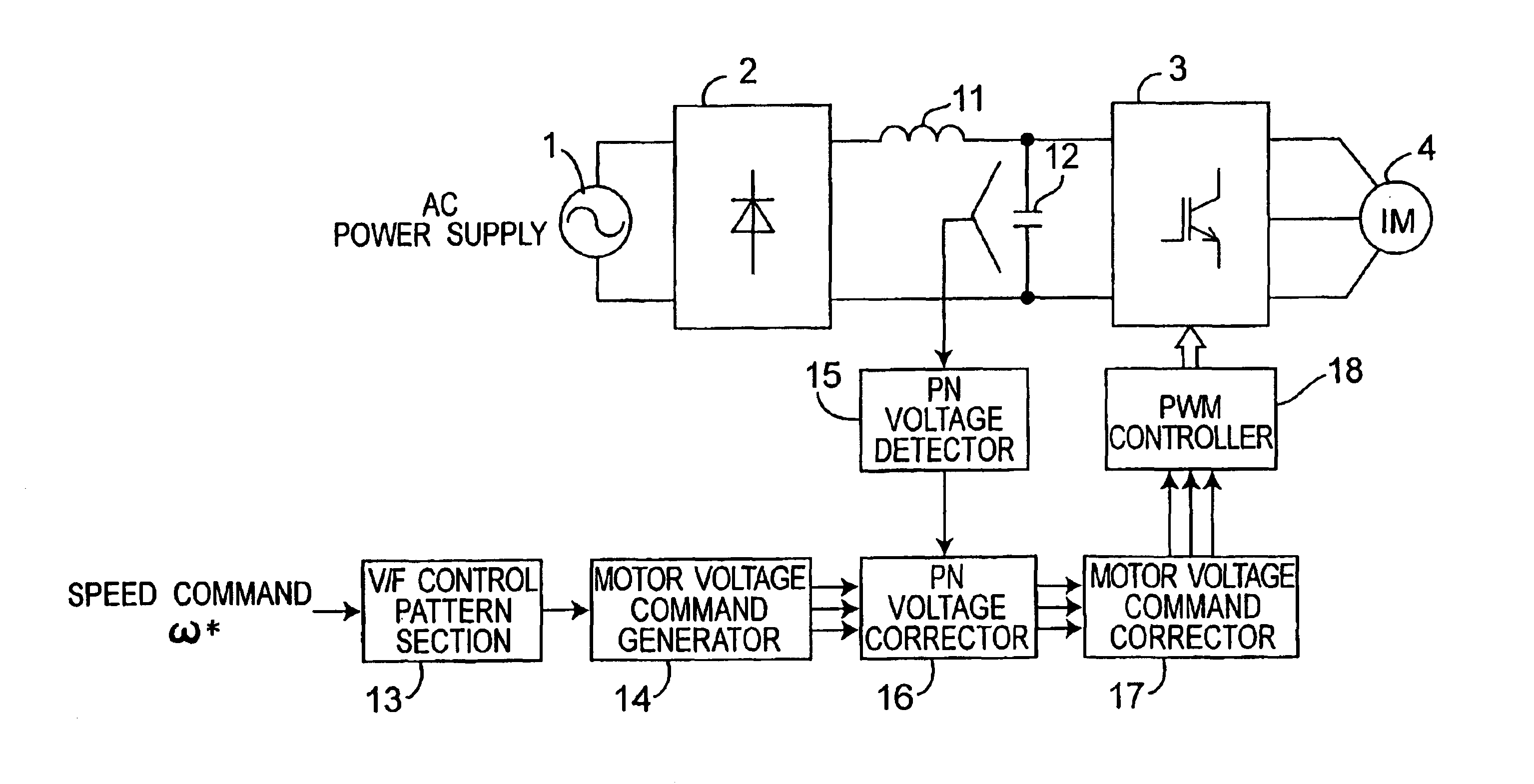
A reactor having a predetermined small capacity is connected to a rectifier, and a capacitor having a predetermined small capacity is connected between DC bus lines of the inverter, so that a small, light and low-cost inverter controller for driving a motor can be implemented, and even when an inverter DC voltage largely fluctuates and it is difficult to drive the motor, the motor can be kept driving by operating the inverter such that a voltage applied to the motor may stay constant by a motor voltage command corrector which generates a motor voltage command correction value of the motor.

Description


Claims


Application Information

Patent Timeline
Owner PANASONIC CORP
Why Eureka
Try Eureka