
Method for performing a hydroforming operation

a technology of hydroforming operation and hollow workpiece, which is applied in the field of hydroforming operation, can solve the problems of large mechanical deformation of hollow workpiece, and achieve the effect of above below the yield strength of the workpi

Active Publication Date: 2006-08-29
METALSA SA DE CV
View PDF10 Cites 8 Cited by
  • Summary
  • Abstract
  • Description
  • Claims
  • Application Information

AI Technical Summary

Benefits of technology

"This patent describes an improved method for hydroforming a workpiece by using a fluid to prevent the workpiece from being deformed inwardly when it is first being enclosed by a pair of opposed hydroforming dies. The method involves gradually increasing the pressure of the fluid inside the workpiece to cause it to deform and engage with the dies. The technical effect of this method is to prevent the workpiece from being deformed too much during the hydroforming process, resulting in a more precise and accurate final shape."

Problems solved by technology

Although the die cavity is usually somewhat larger than the workpiece to be hydroformed, the movement of the two die sections from the opened position to the closed position may, in some instances, cause some mechanical deformation of the hollow workpiece.
However, in some instances, the amount of this mechanical deformation of the hollow workpiece is relatively large.
Such relatively large deformation of the hollow workpiece can be undesirable because it may result in undesirable work hardening of the workpiece and inhibit the free flow of the material of the workpiece during the subsequent performance of the hydroforming operation.

Method used


Image

  • Method for performing a hydroforming operation
  • Method for performing a hydroforming operation
  • Method for performing a hydroforming operation

Examples


Embodiment Construction

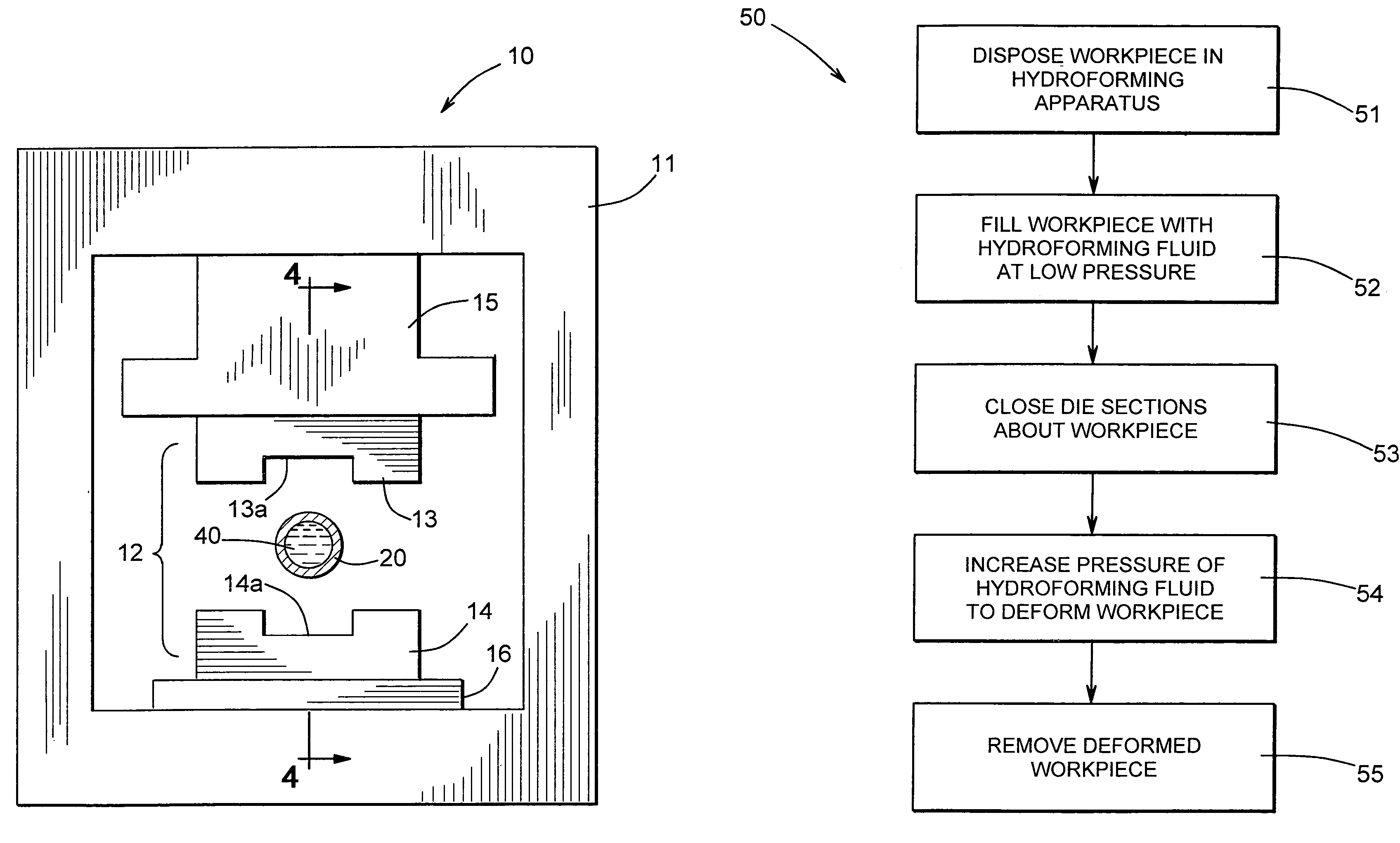
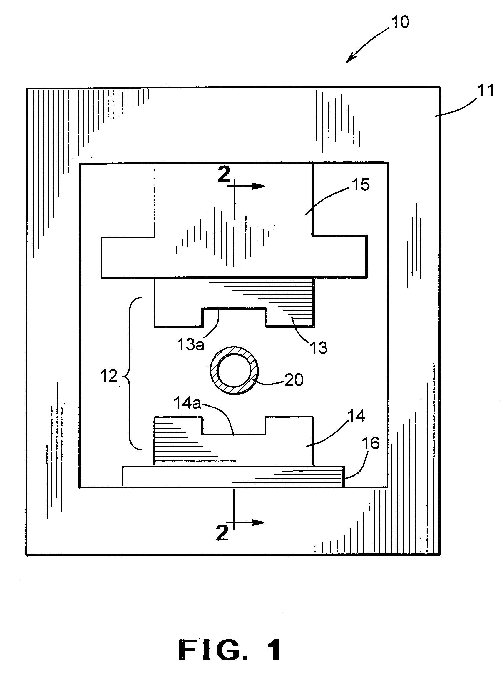
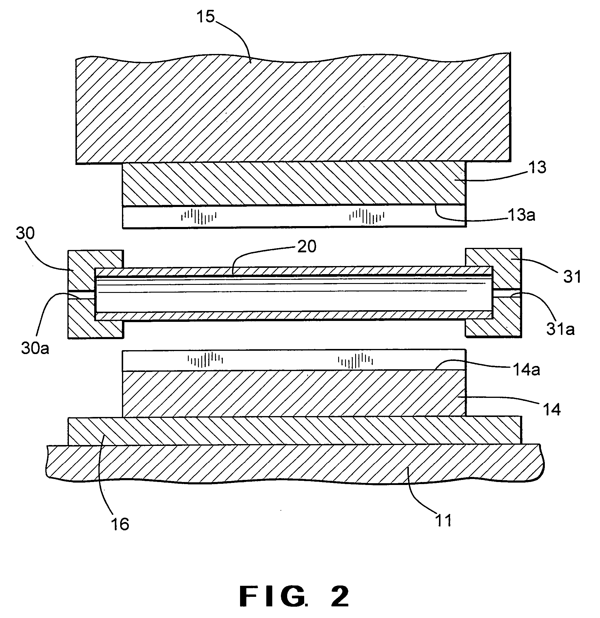
[0015]Referring now to the drawings, there is illustrated in FIGS. 1 and 2 an apparatus, indicated generally at 10, for performing a hydroforming operation in accordance with the method of this invention. The illustrated hydroforming apparatus 10, which is intended to be representative of any structure that is capable of performing the hydroforming operation described below, includes a frame 11 that is sized to support a hydroforming die 12 in a generally vertically oriented relationship. Although this invention will be described and illustrated in the context of a single, vertically oriented hydroforming die 12, it will be appreciated that this invention can be practiced with a greater number of such hydroforming dies if desired. Furthermore, the hydroforming die 12 can be oriented within the hydroforming apparatus 10 in any desired direction other than the illustrated vertical direction, such as in the horizontal direction for example.

[0016]The hydroforming die 12 includes a pair ...


PUM

PropertyMeasurementUnit
pressureaaaaaaaaaa
yield strengthaaaaaaaaaa
shapesaaaaaaaaaa

Abstract

A method for performing a hydroforming operation on a hollow workpiece includes the initial step of filling the interior of the workpiece with a hydroforming fluid. The pressure exerted by the hydroforming fluid against the interior of the workpiece is below the yield strength of the workpiece so as to not change the shape of the workpiece. Then, first and second die sections of the hydroforming apparatus are closed about the workpiece. The movement of the two die sections causes some mechanical deformation of the workpiece, but the presence of the hydroforming fluid within the workpiece prevents the amount of this mechanical deformation of the hollow workpiece from being undesirably large. Thereafter, the pressure exerted by the hydroforming fluid against the interior of the workpiece is increased to above the yield strength of the workpiece. As a result, the workpiece is deformed into engagement with the first and second die sections of the hydroforming die.

Description

CROSS-REFERENCE TO RELATED APPLICATIONS[0001]This application claims the benefit of U.S. Provisional Application No. 60 / 613,819, filed Sep. 28, 2004, the disclosure of which is incorporated herein by reference.BACKGROUND OF THE INVENTION[0002]This invention relates in general to methods for hydroforming hollow or closed channel workpieces to achieve desired shapes. In particular, this invention relates to an improved method for performing a hydroforming operation that resists the tendency of the workpiece to be deformed inwardly upon itself when the closed channel workpiece is initially being enclosed by a pair of opposed hydroforming dies of a hydroforming apparatus.[0003]Hydroforming is a well known metal working operation that uses pressurized fluid to deform a closed channel workpiece, such as a tubular member, outwardly into conformance with a die cavity having a desired shape. A typical hydroforming apparatus includes a frame having two or more hydroforming die sections that a...

Claims


Application Information

Patent Timeline
Patent Type & Authority Patents(United States)
IPC IPC(8): B21D26/02B21D9/15
CPCB21D26/039B21D26/045B21D26/043
Inventor MARANDO, RICHARD A.
Owner METALSA SA DE CV
Learn More