
Vehicle

a technology for wheelchairs and vehicles, applied in the field of vehicles, can solve the problems of restricted movement of wheels in the vehicle transverse direction, difficulty in movement, and difficulty in contacting the wheels of wheelchairs with passengers seated in fixed seats

Active Publication Date: 2021-06-22
TOYOTA JIDOSHA KK
View PDF32 Cites 0 Cited by
  • Summary
  • Abstract
  • Description
  • Claims
  • Application Information

AI Technical Summary

Benefits of technology

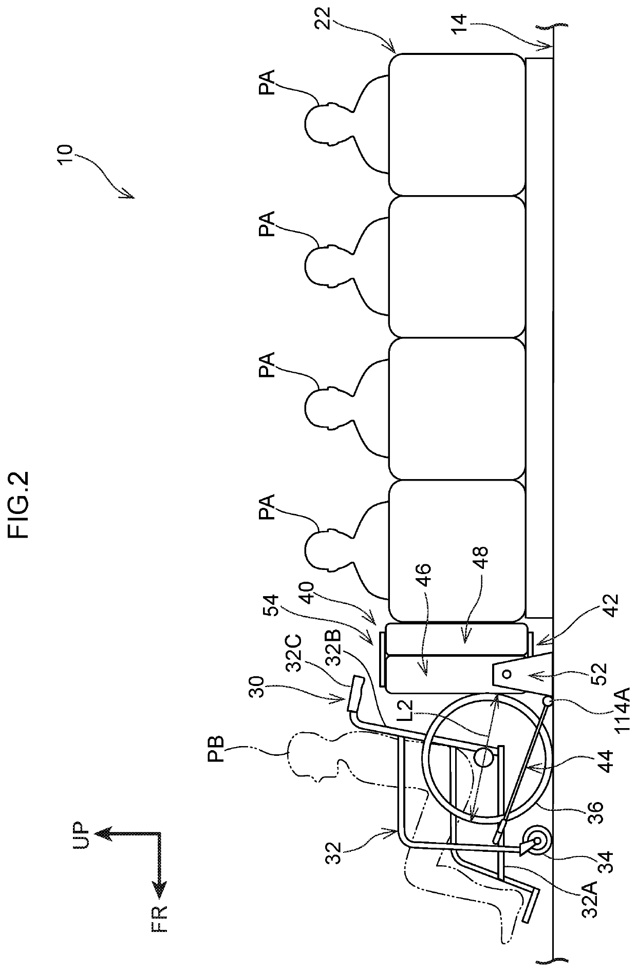
The invention is about a vehicle that can transport wheelchair passengers comfortably. The vehicle has a wheelchair at the front that can be facing the drivers’ direction, allowing the passenger to see the view in front. The wheelchair is supported by the vehicle, so the passenger can pass the time relaxed within the vehicle. In addition, the driver can push the wheelchair into the vehicle, making the wheelchair part of the vehicle and increasing the strength of the wheelchair against the push force. The vehicle also has a contacting member that supports the seat cushion and stabilizes its placement without affecting the wheelchair. Overall, the invention provides improved comfort and safety for wheelchair passengers in vehicles.

Problems solved by technology

In this vehicle, because the wheelchair is placed on the floor portion so as to face in the vehicle longitudinal direction, it is difficult for movement, in the vehicle longitudinal direction, of the passengers who are seated in the fixed seat to be limited by the wheelchair.
Moreover, in this vehicle, because the movable seat exists between the wheelchair and the passengers who are seated in the fixed seat, it is difficult for the wheels of the wheelchair to contact passengers who are seated in the fixed seat.
Further, due to the wheels being made to contact the groove portions, movement of the wheels in the vehicle transverse direction is restricted.

Method used


Image

  • Vehicle
  • Vehicle
  • Vehicle

Examples


modified example

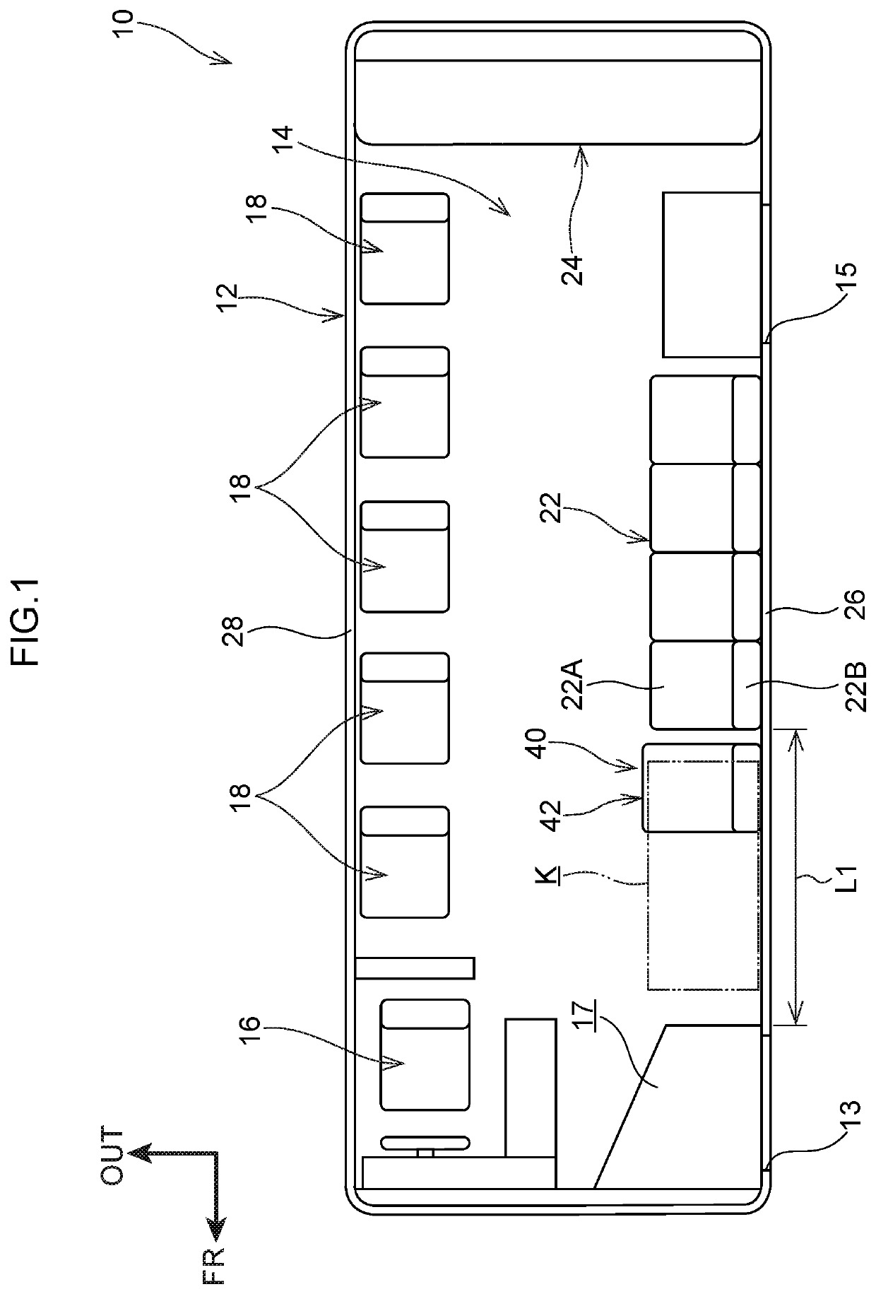
[0105]A bus 110 that serves as an example of a vehicle is shown in FIG. 11. The bus 110 has the inwardly-facing seat 22, and a fixing structure 120 for fixing the wheelchair 30. Further, the bus110 is a structure in which, in the previously-described bus 10 (see FIG. 1), the inwardly-facing seat 22 is set near to the entrance 13 side, and the wheelchair boarding space K is set at the rear side in the vehicle longitudinal direction with respect to the inwardly-facing seat 22 (is set further toward the front side than the exit 15). Note that, in the bus 110, structures other than the inwardly-facing seat 22 and the wheelchair boarding space K are similar to those of the bus 10.

[0106]The fixing structure 120 has a rear side seat 122, which serves as an example of the movable seat, and the fixing members 44. The rear side seat 122 is structured by the same types of members as those of the front side seat 42 (see FIG. 2), but differs with respect to the point that the respective members ...


PUM


Abstract

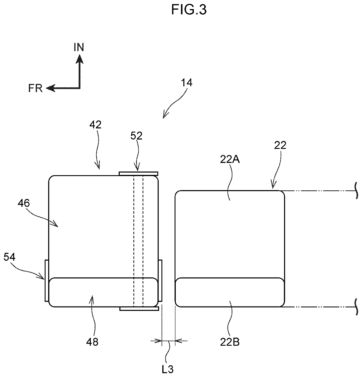
A fixing structure 40 has an inwardly-facing seat 22, a front side seat 42, and fixing members 44. The inwardly-facing seat 22 is fixed to a floor portion 14 such that passengers PA face in a vehicle transverse direction. The front side seat 42 has a seat cushion 46 on which the passenger PA sits, and a supporting member 52, and is disposed at the floor portion 14 at a vehicle longitudinal direction front side of the inwardly-facing seat 22, and rear wheels 36 can contact the seat cushion 46 in a vehicle longitudinal direction. The supporting member 52 supports the seat cushion 46 such that the seat cushion 46 can rotate toward the inwardly-facing seat 22. The fixing members 44 fix a wheelchair 30 to the floor portion 14 in a state in which the rear wheels 36 are made to contact the front side seat 42.

Description

CROSS-REFERENCE TO RELATED APPLICATION[0001]This application is based on and claims priority under 35 USC 119 from Japanese Patent Application No. 2018-155313 filed on Aug. 22, 2018, the disclosure of which is incorporated by reference herein.BACKGROUNDTechnical Field[0002]The present disclosure relates to a vehicle.Related Art[0003]Japanese Patent Application Laid-Open (JP-A) No. 2017-148445 (Patent Document 1) discloses a vehicle in which a wheelchair placement region for the placement of a wheelchair is formed by flipping-up and moving a seat cushion of a passenger seat.[0004]There are vehicles having a fixed seat in which the passengers seated therein face in the vehicle transverse direction. In such a vehicle, the seat cushion is popped-up and a space portion for placement of a wheelchair is ensured by using the structure of Patent Document 1.[0005]Here, in a case in which a wheelchair is placed on the floor portion so as to face in the vehicle transverse direction, because the...

Claims


Application Information

Patent Timeline
Patent Type & Authority Patents(United States)
IPC IPC(8): B60N2/005B60N2/14B60N2/20A61G3/08B62D25/20B62D31/02
CPCA61G3/0808B60N2/005B60N2/20B60N2/14B60Y2200/143B62D25/20B62D31/02A61G3/00B60N2/01B60N2/3011B60N2/3043B60N2/242
Inventor SHIGA, KAZUYUKI
Owner TOYOTA JIDOSHA KK
Learn More