

Ductwork
a technology of ductwork and ductwork, which is applied in the direction of threaded fasteners, valve construction, manufacturing tools, etc., can solve the problem that the flange cannot be mounted from one side of the partitioning, and achieve the effect of simple mounting of the ductwork and yield strength of the brace material
Active Publication Date: 2013-08-22
BLUCHER METAL
View PDF10 Cites 0 Cited by
- Summary
- Abstract
- Description
- Claims
- Application Information
AI Technical Summary
Benefits of technology
The patent is for a simple way to fasten ductwork permanently on one side. The fastening is designed to be tight and secure. The clamping means is limited in its displacement, which reduces stress to a maximum value. This reduces the risk of the ductwork coming loose. By using the operating member, the fitter can be sure that the tightening required by the engineer is achieved.
Problems solved by technology
Moreover, the flange cannot be mounted from one side of the partitioning.
Method used
View moreImage
Smart ImageViewing Examples

Examples
first embodiment
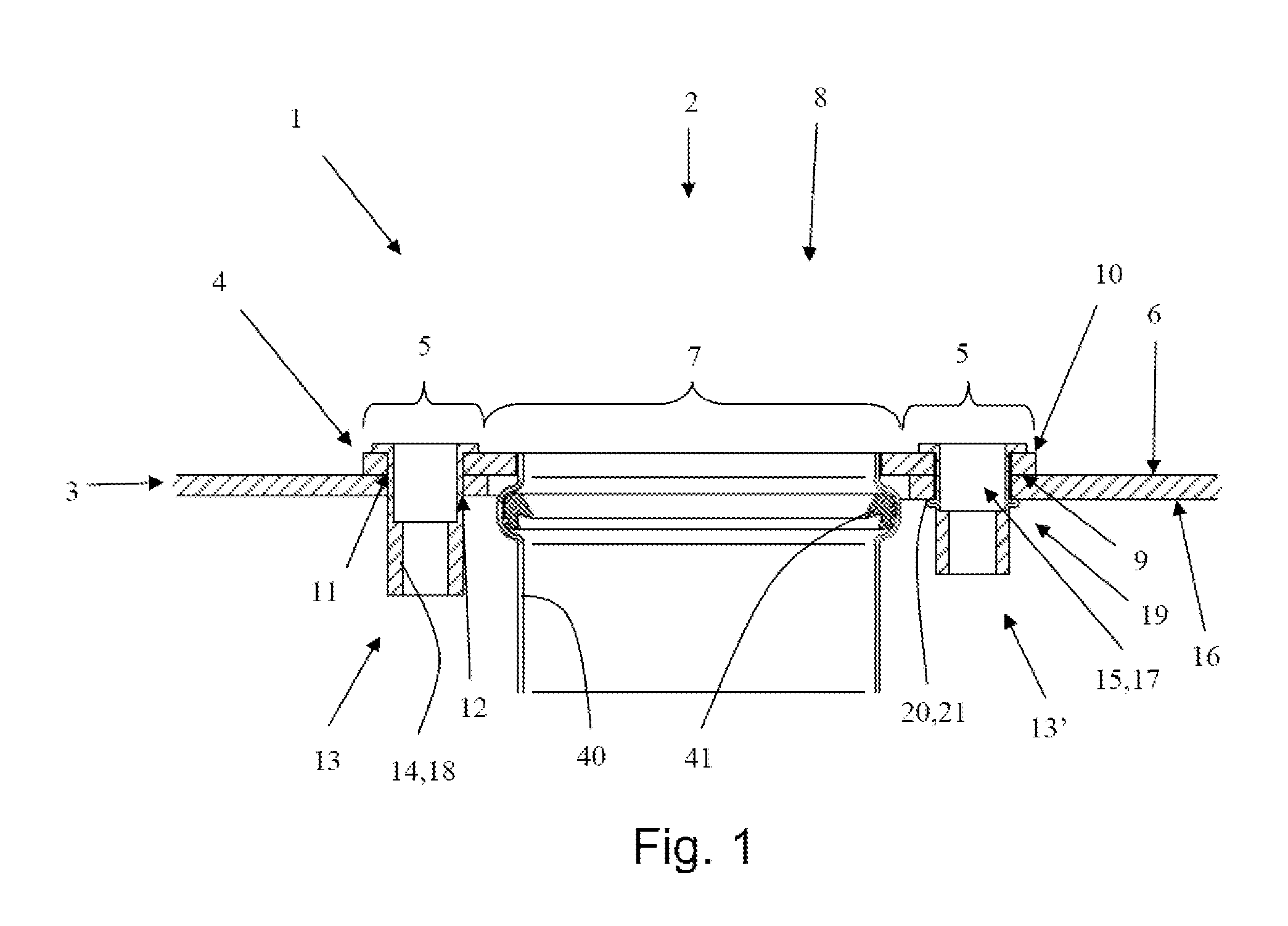
[0063]FIG. 1 shows a cross-section of a ductwork in a first embodiment;
second embodiment
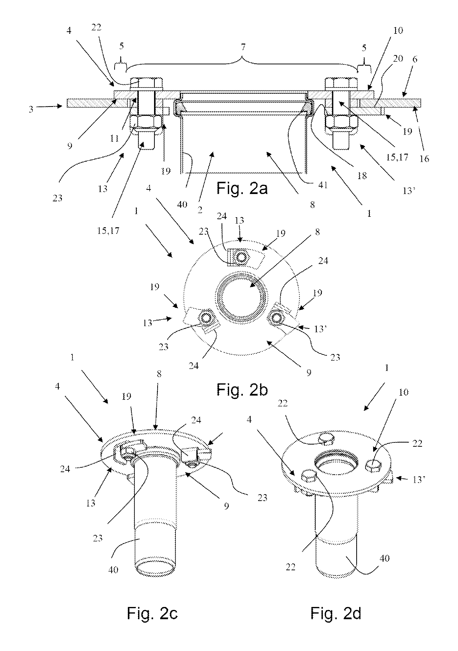
[0064]FIG. 2a shows a cross-section of a ductwork in a second embodiment;
[0065]FIG. 2b shows a plan view of the ductwork shown in FIG. 2a, as seen from the inner side of the flange;
[0066]FIG. 2c shows an isometric view of the ductwork in FIG. 2a;
[0067]FIG. 2d shows a second isometric view of the ductwork in FIG. 2a;
third embodiment
[0068]FIG. 3a shows a cross-section of a ductwork in a third embodiment;
[0069]FIG. 3b shows a plan view of the ductwork shown in FIG. 3a, as seen from the inner side of the flange;
[0070]FIG. 3c shows an isometric view of the ductwork in FIG. 3a;
[0071]FIG. 3d shows a second isometric view of the ductwork in FIG. 3a;
Login to View More PUM
 Abstract
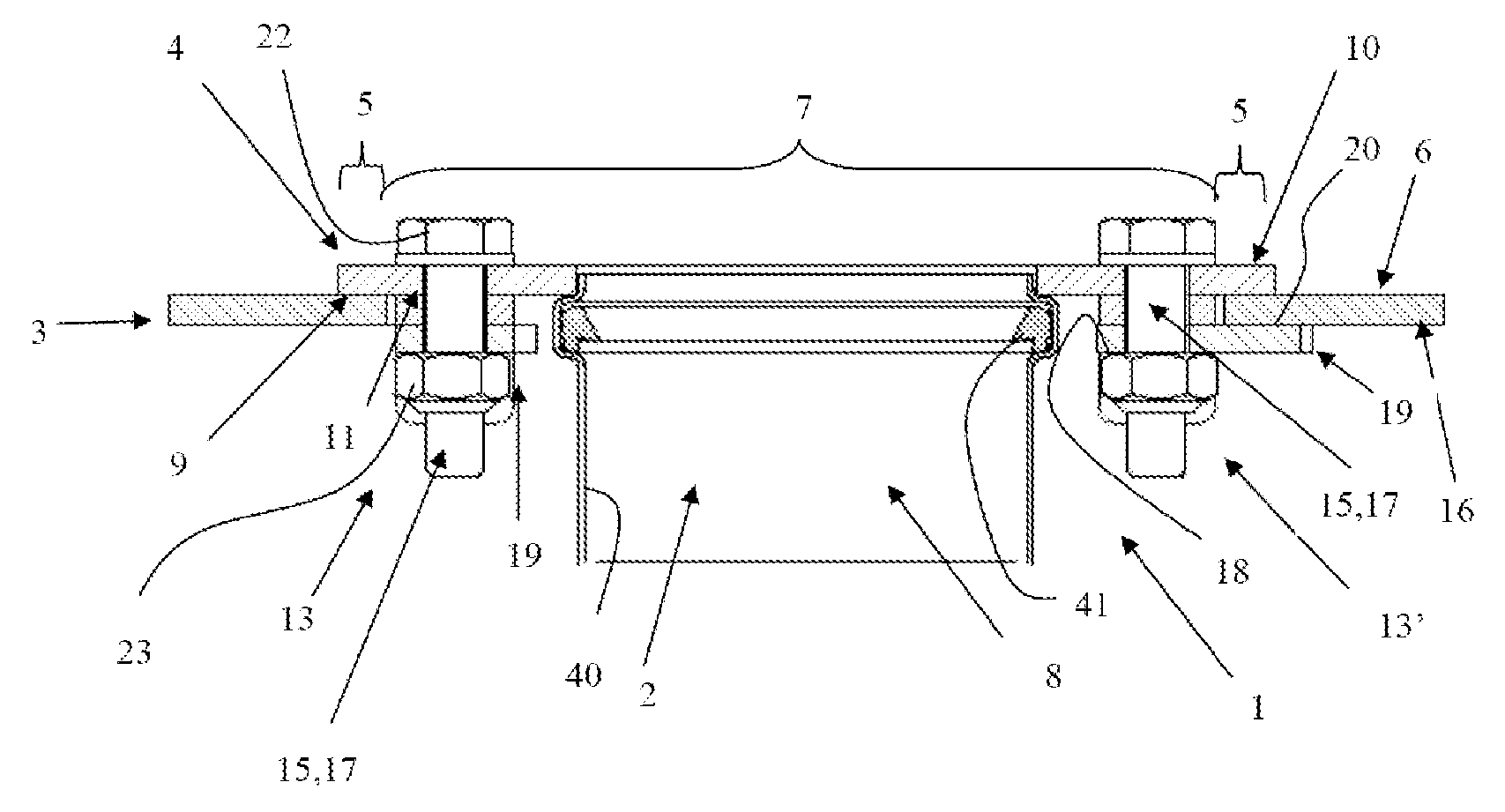
Ductwork (1) for arranging at least one pipe through an opening (2) in a partitioning (3), including a flange (4) having an outer periphery area (5) and a central area (7) which is formed with a guide opening (8) for every pipe, the flange (4) being provided with a number of mounting apertures (11), the flange (4) having an inner side (9) and an outer side (10) opposite the inner side (9), where the inner side (9) is adapted for bearing against one side (6) of the partitioning, wherein the ductwork (1) further includes a connecting arrangement mounted in each mounting aperture (13), the connecting arrangement including force transmission means (15) with an operating member (22) disposed over the outer side (10) of the flange, and with a shank (17) extending through the mounting aperture (11), a clamping means (23) disposed on the shank (17) of the force transmission means and which is displaceable around and / or along the shank (17) by actuating the operating member (22), and an engagement arrangement (19) disposed between the inner side (9) of the flange and the clamping means (23), and which is adapted with contact surfaces (23) interacting with contact surfaces (18) on the clamping means (23), and engaging faces (20) that may be displaced radially relative to the orientation of the shank by actuating the operating member (22).
Description
FIELD OF THE INVENTION[0001]The present invention concerns a ductwork for leading at least one pipe through an opening in a partitioning, including a flange with an outer periphery area and a central area which is designed with a guide opening for every pipe, the flange being provided with a number of mounting apertures, the flange having an inner side and an outer side opposite the inner side, where the inner side is adapted for bearing against one side of the partitioning.BACKGROUND OF THE INVENTION[0002]Ductwork, or lead-ins, are particularly used onboard ships where a pipe is to pass through the partitioning from one compartment to the next compartment. The partitioning can both be the vertically oriented walls separating individual compartments on a deck and the horizontally oriented partitionings separating individual decks.[0003]Ductwork made of metal may e.g. be fastened to the partitioning by welding, on the condition that both parts are made of a weldable metal. This techn...
Claims
Login to View More Application Information
Patent Timeline
 Patent Type & AuthorityApplications(United States)
IPC IPC(8): F16L5/08
CPCB63B13/00F16B13/0833F16B13/0891Y10T16/05F16L5/025F16L5/08F16B37/067F16B13/06F16B13/08
InventorLOHMANN, HANS
OwnerBLUCHER METAL