
Adjustable wrench

a technology of adjustable wrenches and wrenches, which is applied in the direction of wrenches, screwdrivers, manufacturing tools, etc., can solve the problems of reducing the ability of the movable jaw to reliably hold a secure position, cutting knuckles, and injury to the user's hand, so as to facilitate manual movement of the movable jaw member

Inactive Publication Date: 2006-08-29
SHERBURNE HOLLIS B
View PDF22 Cites 7 Cited by
  • Summary
  • Abstract
  • Description
  • Claims
  • Application Information

AI Technical Summary

Benefits of technology

"The present invention is an adjustable wrench assembly for loosening or tightening a fastener. It includes a handle, a movable jaw, a beam, and a trigger. The handle has a fixed jaw segment and a channel, and the movable jaw has a jaw segment and an engagement portion that moves between an open and closed state. The beam is slidably engaged in the void and has a serrated toothed rack that engages with the movable jaw's serrated toothed rack to secure the movable jaw. The trigger is attached to the movable jaw and can move it between the open and closed state. The technical effect of this invention is an adjustable wrench assembly that allows for easy and secure adjustment of the jaw size and position, making it easier to tighten or loosen fasteners."

Problems solved by technology

One issue with the crescent wrench is the speed of adjustment that is attainable, thus to have a higher speed of adjustment with the worm gear and thumb wheel would require a steeper helical angle to be constructed for the cut of the worm gear, however, this steeper angle decreases the ability of the movable jaw to reliably hold a secure position upon the fastener, especially when the fastener is under a high level of force as against movable jaw, in effect causing the worm gear to rotate in a manner to loosen or in other words drive the two jaw faces apart.
This results in causing the problem of rounding off of the fastener points which is undesirable and can also cause injury to the user's hand, in that as the wrench slips around the points of the fastener while the user is applying force to the end of the handle furthest from the jaws can result in scraped and cut knuckles.
Another drawback of the typical traditional crescent wrench, is that in order to adjust the jaws relative to one another the user's hand must move from its advantageous position on the handle which is at the furthest distance from the jaw portion of the handle that results in maximum torque applied from the force of the user's hand, wherein the users hand to adjust the jaws relative to one another must be moved toward the jaw portion of the handle for the user's fingers to engage the worm gear to facilitate jaw adjustment.
This requirement of the user having to move their hand on the handle of the wrench can be especially inconvenient when the wrench is being used in a tight or confined space around the fastener.
Thus, the aforementioned description of a typical crescent wrench has identified three major problems, the first problem being the slow speed of adjustment between the jaws, the second problem being the inconvenience of the user having to reposition their hand on the handle to make the jaw adjustment, and the third problem being the lack of a secure holding of a position of the movable jaw especially while under load from the function of tightening or loosening the fastener causing not only damage to the fastener itself but also potential injury to the user's hand.
Although Garrison overcomes the problem of the movable jaw not being securely locked in position by virtue of the toothed rack interface, there is a problem in that the movable jaw must be manually positioned by the user's second hand as against the fastener while the users first hand must manually hold the rod away from the movable jaw segment at the same time, this can be especially difficult in tight or confined areas around the fastener.
None of the aforementioned prior examples address the problem of the speed with which the movable jaw can be placed into its selected position and all require the use of two hands to both manually disengage the rod serrated tooth interface from the movable jaw serrated tooth interface and at the same time requiring the user to manually move the movable jaw into the selected position, consuming both of the user's hands at the same time and causing difficulty where there is a tight or confined space around the fastener.
Other prior art approaches to the manually adjustable wrench have a higher degree of complexity such as in U.S. Patent Application Publication No. U.S. 2002 / 0112574 A1 to Marks that discloses a slide switch adjustable wrench, allowing through a mechanical linkage adjustment of the movable jaw from the handle portion opposite of the jaw portion thus overcoming the two hands required problem as previously discussed and assisting in the speed of adjustment issue of the movable jaw, however, as Marks still uses the helical thumb wheel to adjust the movable jaw there's still the aforementioned issue of the movable jaw not being secured in a selected position as against the fastener.
Another solution is given in U.S. Pat. No. 5,375,490 to Carlmark that utilizes an adjustable spanner having a crescent gear segment meshed with a toothed rack on the movable jaw with the disadvantage being, of having to initiate a separate locking device to fix the movable jaw position.

Method used


Image

  • Adjustable wrench
  • Adjustable wrench
  • Adjustable wrench

Examples


Embodiment Construction

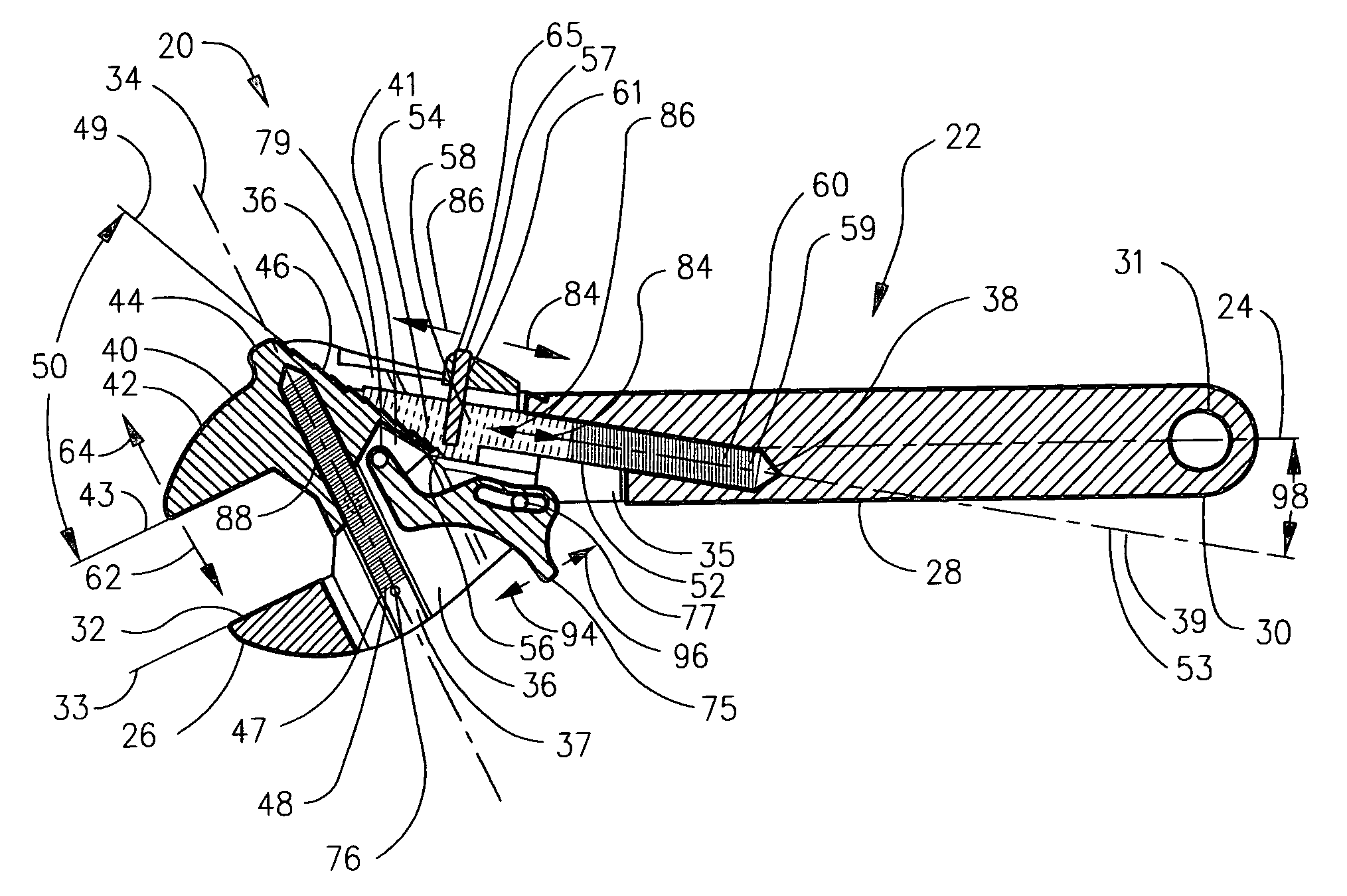
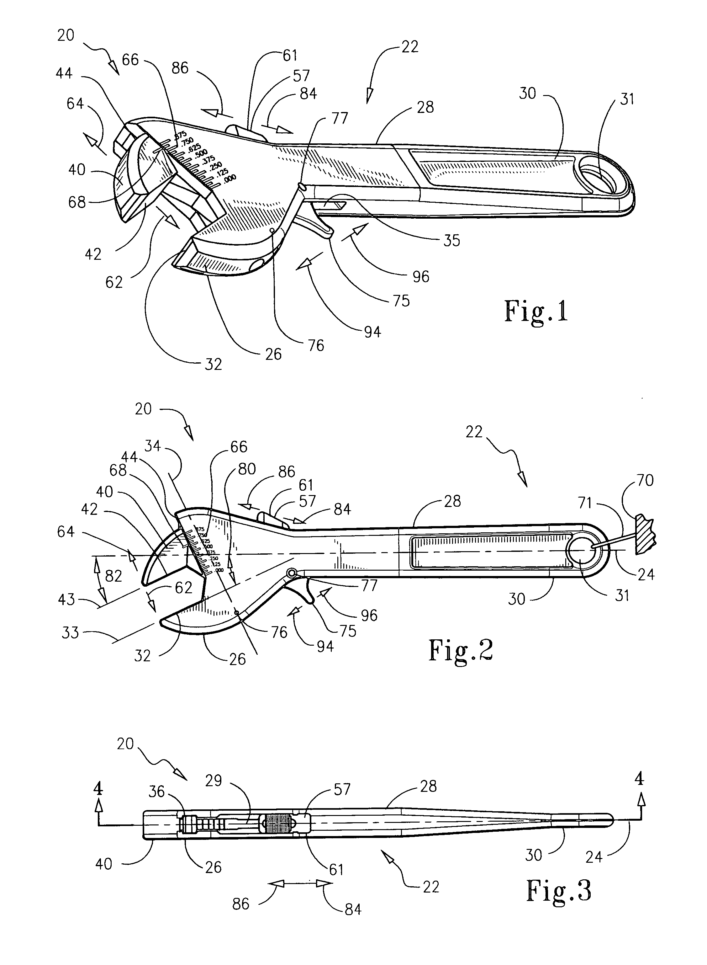
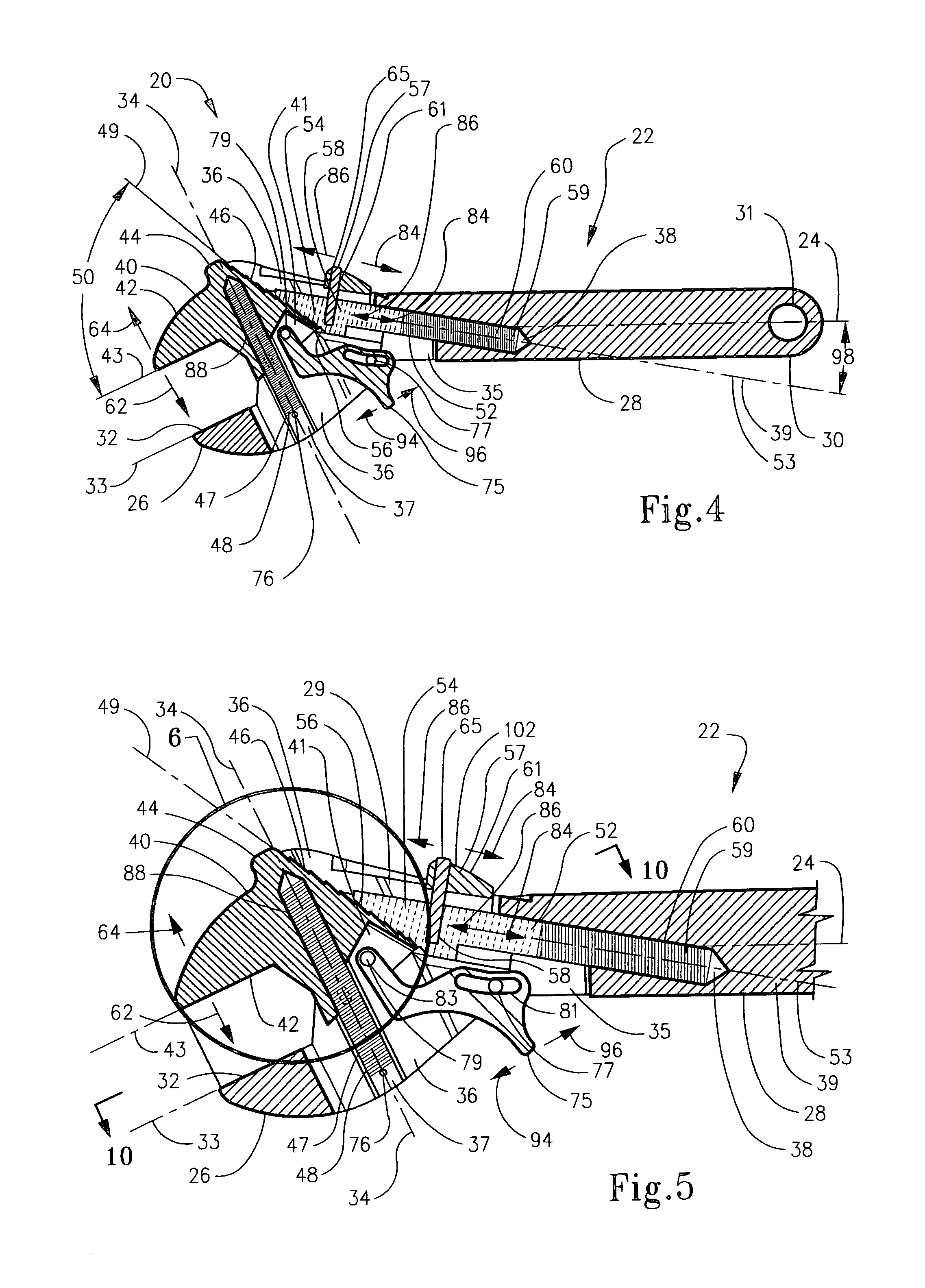
[0108]With initial reference to FIG. 1 shown is a perspective view of the adjustable wrench assembly 20 with the movable jaw member 40 moved toward the open state, FIG. 2 shows a side view of the adjustable wrench assembly 20 with the movable jaw member 40 moved toward the open state, with the wrench 20 suspended from the support member 70 through use of the suspension element 71, and FIG. 3 shows a view of the adjustable wrench assembly 20 from the movable jaw member 40 end. Further, FIG. 4 shows crossectional cut 4—4 from FIG. 3, depicting the broad general interface between the movable jaw member 40, the beam 52, the trigger 75, and the handle member 22 along with the means 59 for urging the beam 52 and the means 47 for urging the movable jaw member 40. Continuing, FIG. 5 shows an expanded view of the broad general interface between the movable jaw member 40, the beam 52, the trigger 75, and the handle member 22 along with the means 59 for urging the beam 52 and the means 47 for ...


PUM


Abstract

An adjustable wrench and method for loosening or tightening a fastener includes a handle member having a fixed jaw segment, a substantially transverse channel therethrough, and a void in communication with the channel. Also, a movable jaw member having a serrated toothed rack that is slidably engaged within the channel. In addition, a beam that is slidably engaged within the void, the beam including a toothed rack that selectably matably engages with the movable jaw toothed rack to help secure the jaw in position. Finally, included is a trigger member that is pivotally attached to the movable jaw member and is slidably engaged with the handle member, the trigger facilitates manual movement of the movable jaw from the closed state to the open state and vice versa, when the movable jaw toothed rack and the beam toothed rack are selectively disengaged.

Description

TECHNICAL FIELD[0001]The present invention relates generally to adjustable wrenches. More particularly, the present invention relates specifically to manually hand operated adjustable wrenches having variable jaw adjustment within a range, for use with a particular size fastener, wherein the wrench jaw is activated to close down and secure upon the fastener for tightening or loosening of the fastener until the adjustable jaw is manually unsecured.BACKGROUND OF INVENTION[0002]Manually hand operated adjustable wrenches having variable jaw adjustment within a range, for use with a particular size fastener are old in the art. The most traditional type is typically called a crescent wrench. The design of a crescent wrench includes a movable jaw slide and a guide track that is opposed to a fixed jaw, wherein the movable jaw is adjusted by means of a worm gear that is supported within the housing that forms an end portion of the adjustable wrench handle. Typically, the worm gear functions ...

Claims


Application Information

Patent Timeline
Patent Type & Authority Patents(United States)
IPC IPC(8): B25B13/22
CPCB25B13/22B25B13/18
Inventor SHERBURNE, HOLLIS B.
Owner SHERBURNE HOLLIS B
Learn More