Hydraulic radial bearing

Active Publication Date: 2006-08-29
CONTITECH VIBRATION CONTROL
View PDF9 Cites 3 Cited by
  • Summary
  • Abstract
  • Description
  • Claims
  • Application Information

AI Technical Summary

Benefits of technology

[0006]It is an object of the invention to provide a simply configured radial bearing of the kind referred to initially h

Problems solved by technology

Conventional standard hydro bushings are completely unsuited for damping in the lower hearing range.
A further disadvantage is that additional

Method used


Image

  • Hydraulic radial bearing
  • Hydraulic radial bearing
  • Hydraulic radial bearing

Examples


Example

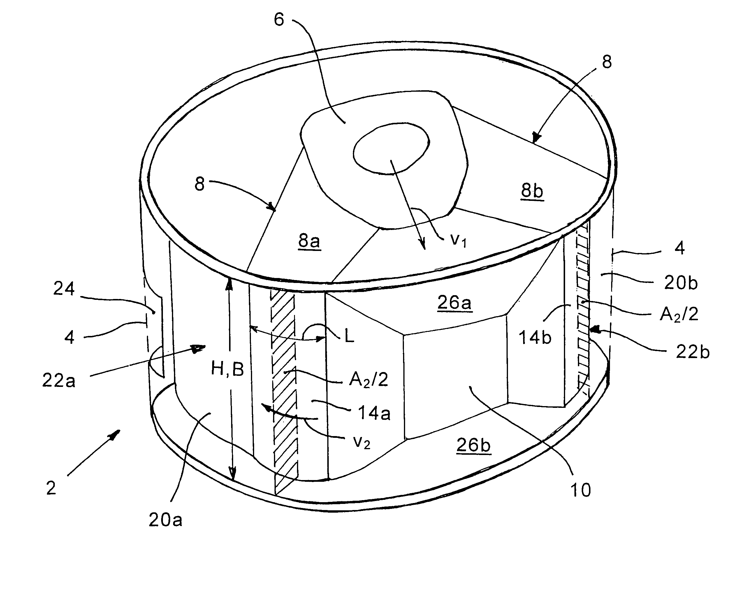
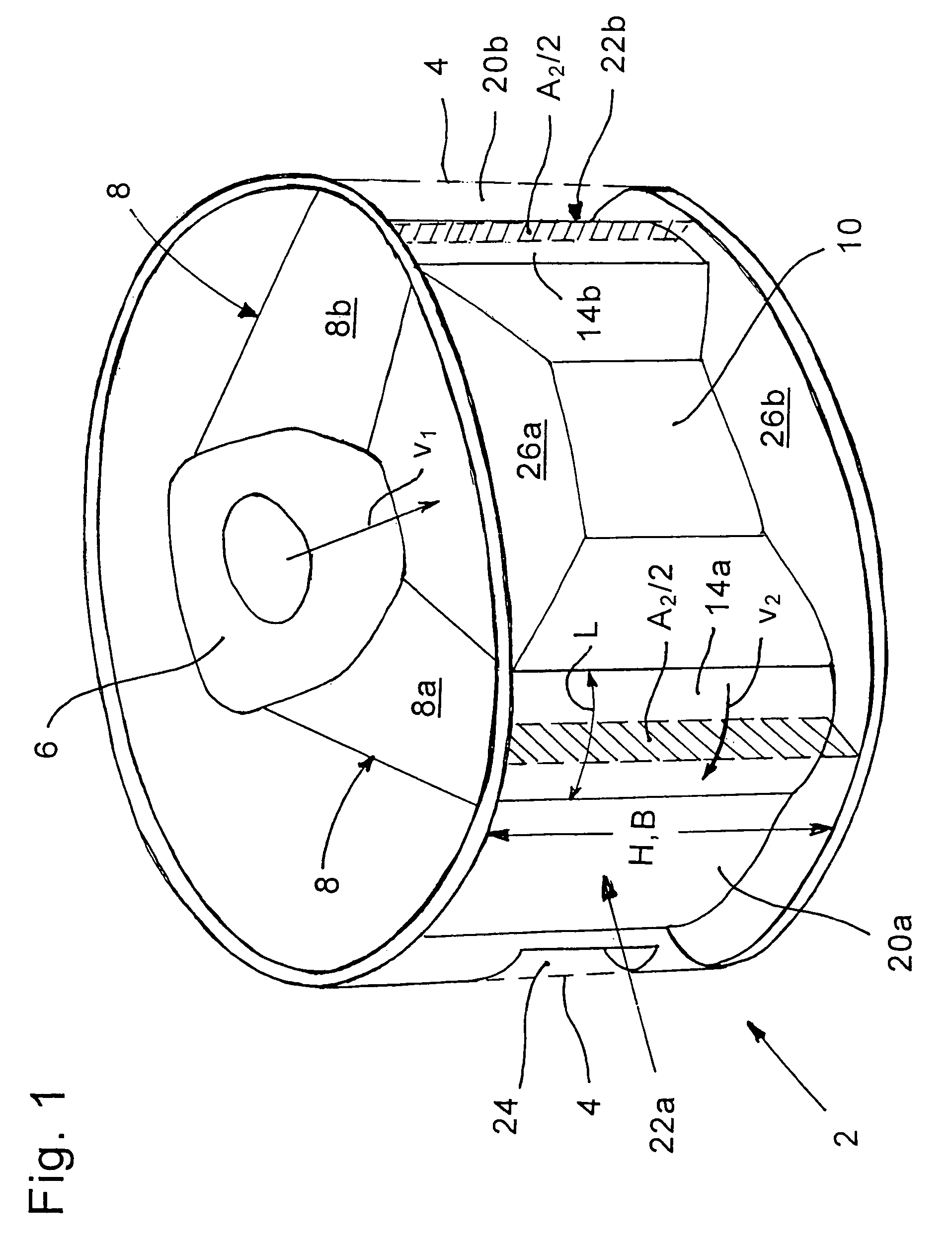
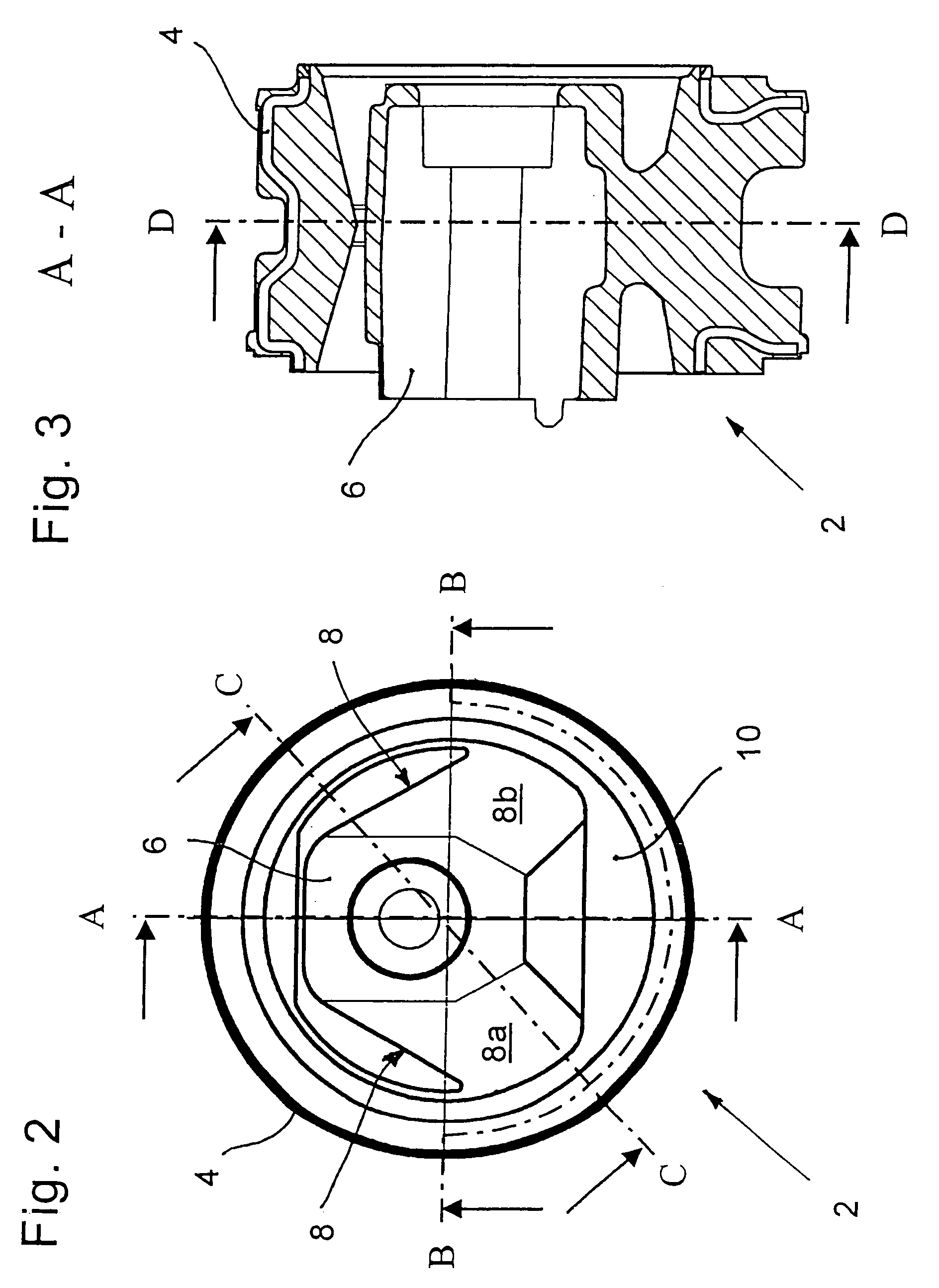
[0018]The standard hydro bushing 102 shown in FIG. 7 essentially comprises: a sleeve-shaped outer body 104 (shown in phantom outline); an inner mounting body 106 (for accommodating a bearing lug) which is spaced radially to the outer body 104; and, a two-legged spring body 108 disposed between the outer body 104 and the inner body 106.

[0019]A volume-changeable work chamber 110 is filled with hydraulic liquid and is disposed between the legs (108a, 108b) of the spring body 108. The work chamber 110 is delimited from the outside by the outer body 104 and on both sides by respective massive legs (112a, 112b). A transfer channel 114 is arranged annularly at the inner side of the outer body 104 and extends peripherally. One end of the transfer channel 114 has an opening 116 to the work chamber 110 and the other end has an opening 118 to a compensating chamber 120a arranged to one side in the bearing 102. The compensating chamber 120a is likewise delimited toward the outside by the cylind...


PUM


Abstract

A work chamber is filled with a hydraulic liquid and is disposed between the legs of the spring body of a hydraulic radial bearing. The work chamber is connected to a compensating chamber via a transfer channel. The desired absorption of disturbing noises in the region of 130 Hz is obtained with a special dimensioning of the cross-sectional area of the work chamber, the dynamic swell stiffness of the spring body and the length (L) and the total cross-sectional area (A2) of the transfer channel. The ratio of the effective cross-sectional area (A1) of the work chamber to the cross-sectional area (A2) of the channel lies preferably between 0.1 and 10 while the ratio of the length (L) of the transfer channel to the total cross-sectional area (A2) of the transfer channel is in the range of 0.1 to 4.0.

Description

FIELD OF THE INVENTION[0001]The invention relates to a hydraulic radial bearing, a so-called hydro bushing as they are used for mounting engines in motor vehicles.BACKGROUND OF THE INVENTION[0002]In addition to the insulation of vibrations, which is also provided by conventional rubber elements, the hydro bushings include a damping characteristic for damping the vibrations occurring in the vehicle between the engine and the chassis. As described with respect to FIG. 7, the damping characteristics are achieved with a system integrated into the hydro bushing. This system comprises a support spring, which acts as a piston, and a channel. Here, the mass in the channel and the volume stiffness form a vibration-capable system.[0003]Such systems are matched to approximately 10 Hz and are therefore able to compensate for the inherent vibrations of the engine. Conventional standard hydro bushings are completely unsuited for damping in the lower hearing range.[0004]The invention is directed t...

Claims


Application Information

Patent Timeline
IPC IPC(8): F16F5/00F16F13/14B60K5/12
CPCF16F13/1463F16F13/1427B60K5/1208
Inventor RICHTER, MATTHIASBERGE, FALKHOLST, MEINERTROOS, JURGEN
Owner CONTITECH VIBRATION CONTROL
Why Eureka
Try Eureka