
Wire identifier

Inactive Publication Date: 2006-08-29
KIM DAE S
View PDF11 Cites 4 Cited by
  • Summary
  • Abstract
  • Description
  • Claims
  • Application Information

AI Technical Summary

Benefits of technology

[0009]This invention provides an efficient means for identifying each set of wires from a multiple of substantially identical sets of wires at the distributed end. This invention is particularly effective for minimizing time, labor, and mistake in installing residential or a small commercial electric service with less than two dozen circuit breakers.

Problems solved by technology

None of these improvements brought a simple, reliable and robust tool which an electrician can carry in his pocket and save time and money in his work.

Method used


Image

  • Wire identifier
  • Wire identifier

Examples


Embodiment Construction

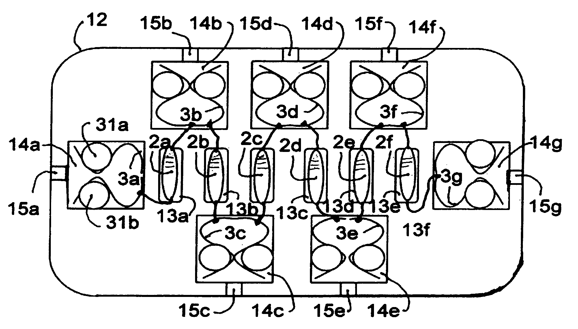
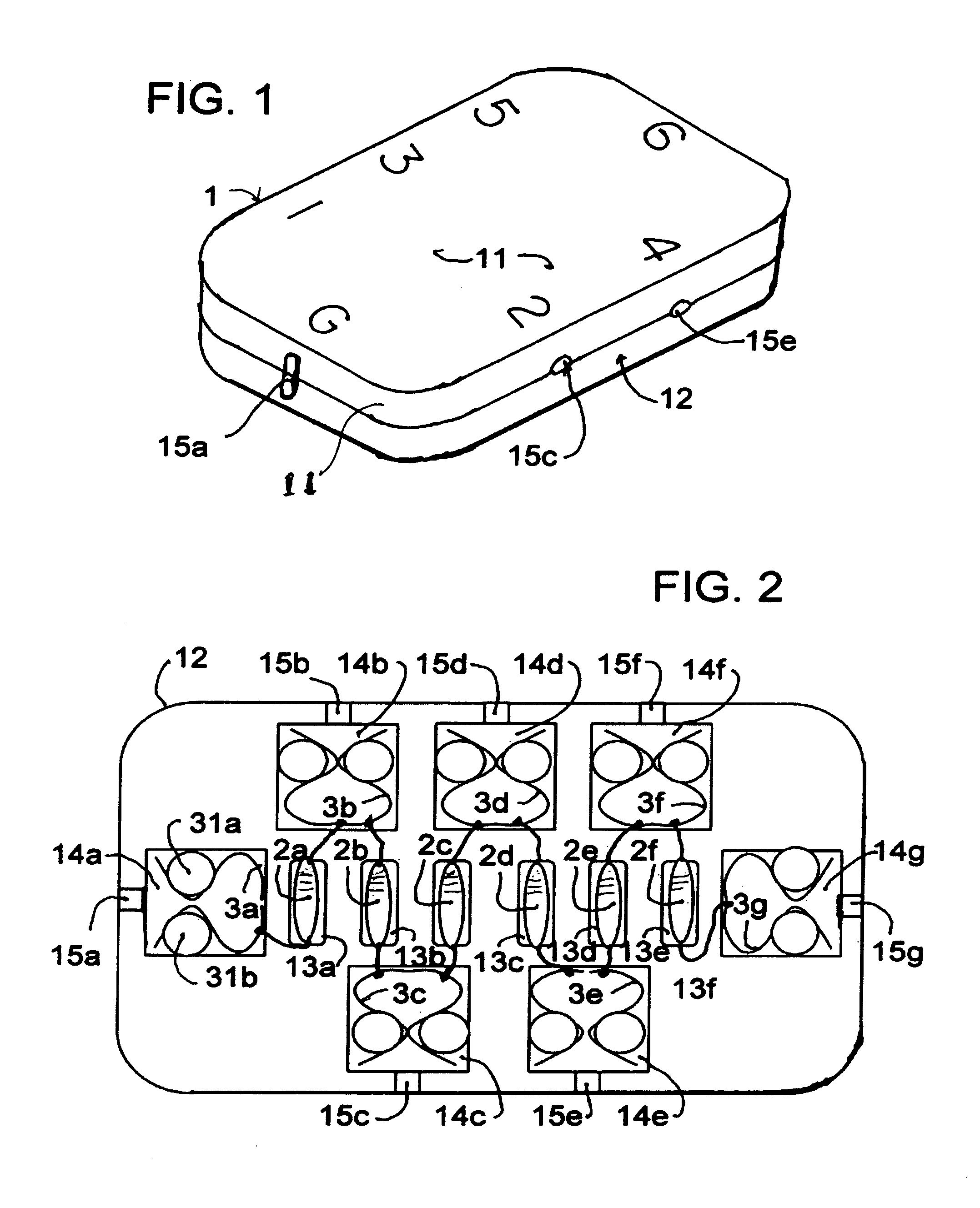
[0020]In FIG. 1 and also FIG. 2, in detail, this invention comprises of an electrically insulated housing 1 which is formed by joining a pair of molded thermo-plastic clam-shell halves 11 and 12, six substantially identical 10 K Ohm resistors, 2a, 2b, 2c, 2d, 2e and 2f, connected in series and seven metal wire holding means 3a to 3g, which are connected to two ends and five junctions between neighboring resistors.

[0021]The clam-shell halves 11 and 12 are identical and provide each halves of cavities 13a to 13f for resistors 2a to 2f and of larger cavities 14a to 14g for wire holding means 3a to 3g and openings 15a to 15g for inserting wires when joined. Both halves 11 and 12 are substantially rectangular and have smoothly rounded corners. The openings are sufficiently large to accommodate for ten gage wire which is largest in common use. However, two openings 15a and 15g located at the middle of the short sides of the housing 1 are elongated to hold an additional wire. The legs of t...


PUM


Abstract

A device and method for identifying each set of wire from a multiple of substantially identical sets of wires at the distributed end includes of a multiple of substantially identical resistors connected in series, metal wire holder connected to the each junctions and to the each ends and an electrically non-conducting housing with a multiple of openings for inserting wires to connect to each wire holder. The resistance between the first wire holder at one end and each successive wire holder increases in a finite step and corresponds to the markings on the housing. When all ground wires are connected to the first wire holder and each hot wire are connected the successive wire holders at the distributing end, the resistance between the ground wire and the hot wire identifies each set at the distributed end.

Description

BACKGROUND OF THE INVENTION[0001]1. Field of the Invention[0002]This invention relates to a device and method for identifying each set of wires among multiple of substantially identical sets of wires at the distributed ends.[0003]2. Descriptions of the Prior Arts[0004]During installation of electric service in a new building, renovation of electric wiring in an old building or installation of telephone wires for a residential or a small commercial building, an electrician connects a power source, sometimes, a vibrating buzzer, to a selected pair of wires at the central distributing end and then he identifies that particular pair at the distributed terminal end by detecting a light or sound, respectively.[0005]Another method is simply to short a select pair of wire at one end and hunt for the pair at the other end with a portable power source and indicator such as a flash light with connecting clips. The time for traveling between two ends for repeating this process is minimized by t...

Claims


Application Information

Patent Timeline
IPC IPC(8): G01R19/00G01R31/02
CPCG01R31/041G01R31/023G01R31/60G01R31/67
Inventor KIM, DAE S.
Owner KIM DAE S
Learn More