
Mop and container system for the drainage of liquids

a container system and liquid drainage technology, applied in the field of mechanical cleaning systems, can solve the problems of loss of energy and complex maintenance, increase in volume, manufacturing cost, etc., and achieve the effect of easy collection of solid particles

Inactive Publication Date: 2014-03-04
VILA FERNANDEZ RICARDO JOSE +1
View PDF3 Cites 0 Cited by
  • Summary
  • Abstract
  • Description
  • Claims
  • Application Information

AI Technical Summary

Benefits of technology

[0013]An objective of the invention is to provide a mechanical cleaning system that during the use of a cleaning mop and floor drying, etc., in homes and other places, as well as during the liquid extraction operation from the mop, allows to perform the above mentioned operations with greater comfort, more efficiency and speed as well as hygienically and with no risk of injury to the user, and that the liquid extraction from the mop is carried out with the least effort. The present invention provides the maximum possible simplicity for the purpose of minimizing the number of pieces and weight, making it easy to manufacture and use.
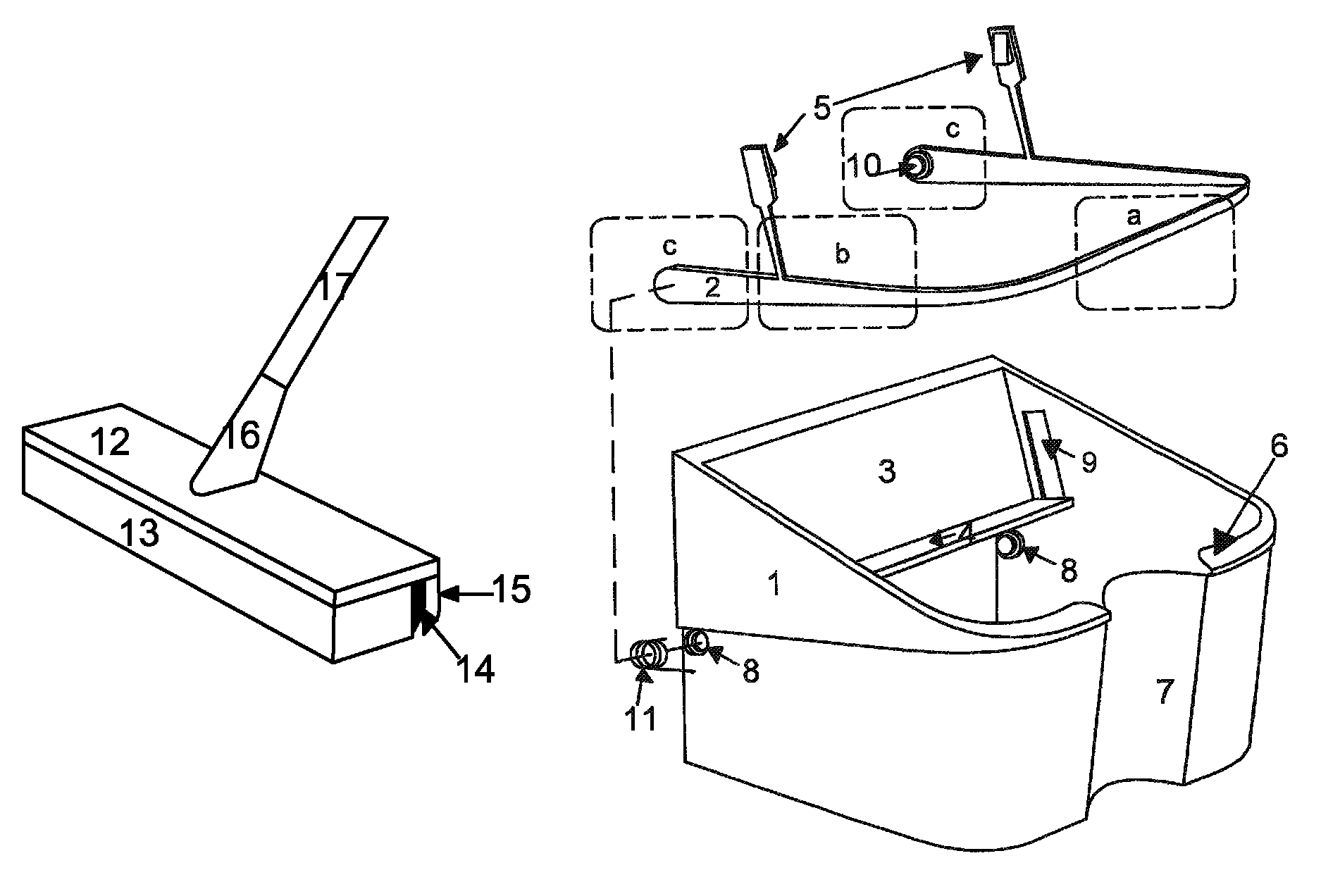
[0014]The system comprises a container with a multifunction element handle-lever-pedal, and a mop. The container is a recipient designed not only to contain water and detergent and to be a dirty water deposit, but to integrate the liquid extraction system of the mop. The multifunction element handle-lever-pedal which forms part of the container is a one-piece device with sections having diverse functions. The pedal section is designed to receive the force exerted by the user. Said force is transmitted by the lever section to extensions belonging to the multifunction element, said extensions being located in the lever section. The extensions end in hooks to press the mop inside the container and to allow extracting liquids and solid particles from the mop. Then, the drainage is done by mechanical pressing in a practical, comfortable, simple, and efficient way. The manufacture cost of the container with the multifunction element handle-lever-pedal is low, since a single matrix is sufficient.
[0015]It is another objective of the present invention to better use the force exerted by the pressure from the pedal section of the multifunction element handle-level-pedal, since the path of the pedal section is 5 to 6 times greater than the path of the hooks used to press the mop achieving an excellent conversion to a path 5 to 6 times smaller, but with an increase of 5 to 6 times the force exerted on the pedal section. Between the pedal section and the hooks that exert the force, it has absolutely removed all kinds of mechanisms because they lead to a loss of energy and complex maintenance, increase in volume, and manufacturing costs. A one single multifunction element handle-lever-pedal is therefore designed to do all the tasks, making more efficient the use of the pressure exerted on the pedal section, thus achieving a very lightweight pedal section with a tremendous pressure on the mop, that provides a draining power that exceeds the necessary in absolutely all of the cases. The purpose is to have a long path of the pedal section and shortening of the compression path of the mop, increasing proportionally to the force.
[0016]It is also an objective of the present invention to make it easy to drain, clean, and store the device.
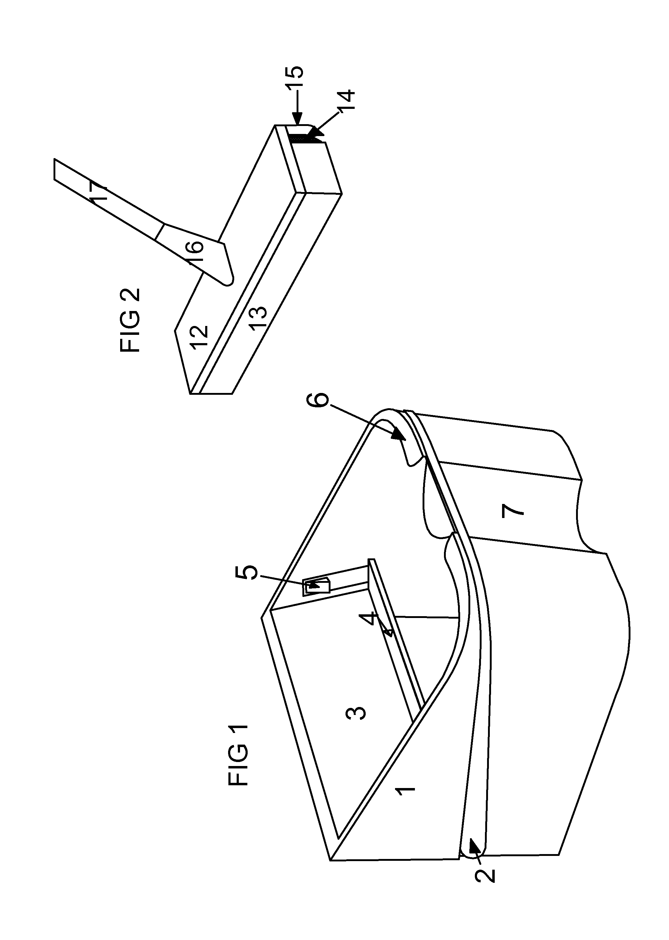
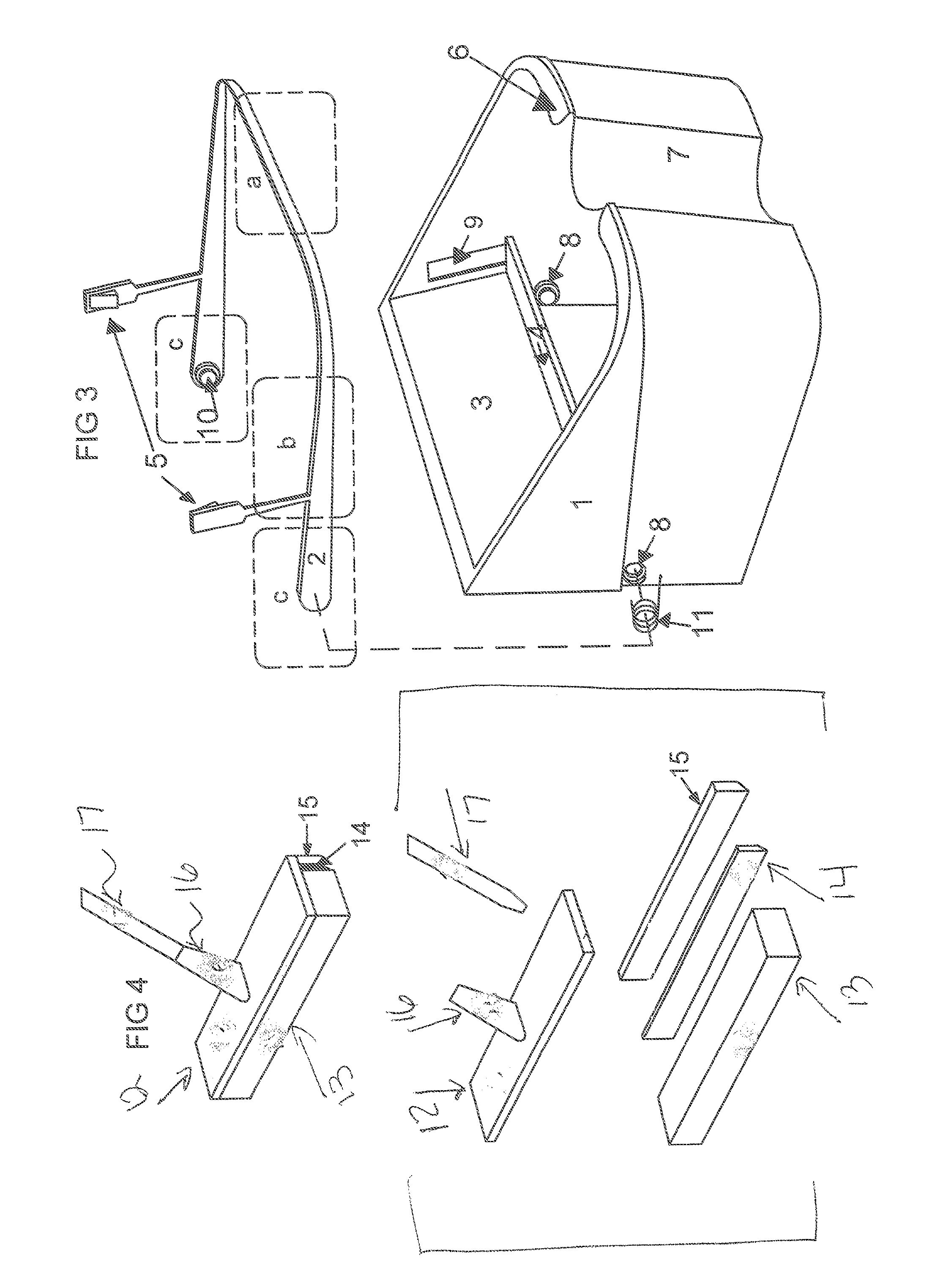
[0018]The multifunction element handle-lever-pedal is a one piece device having a U-shape that matches the shape of the container in the horizontal direction. The handle-lever-pedal includes in the internal ends of the arms of the U, two small cylinders (hereafter referred to as insertion cylinders), one on each arm. Each one of the insertion cylinders are inserted and wrapped in one spring in the side hollows of the container to attach the handle-level-pedal to the same. In each of the arms of the U, includes an extension having the shape of a prism parallelogram of small thickness that ends in its upper end with a hook oriented towards the interior of the U. These extensions are located in the lever section as described below. The hooks are coupled in the lateral openings of the container towards the inside of the same to press the mop. The curve of the U is the pedal section located at the front side of the container, the central depression on the front wall of the container facilitates the pressure on the pedal section, for example, with the foot. The arm of the U is the lever section because it describes an upward-downward movement during the pressure and the release of the pedal section. The lever section transmits a force to the extensions on the multifunction element and the extensions to the hooks that press the mop on the back support table for supporting mops. The entire U comprises, in turn, the handle of the container. In the insertion cylinder section there are small cylinders that are wrapped in springs that connect the handle-lever-pedal to the container.

Problems solved by technology

Between the pedal section and the hooks that exert the force, it has absolutely removed all kinds of mechanisms because they lead to a loss of energy and complex maintenance, increase in volume, and manufacturing costs.

Method used


Image

  • Mop and container system for the drainage of liquids
  • Mop and container system for the drainage of liquids
  • Mop and container system for the drainage of liquids

Examples


Embodiment Construction

[0036]The liquid drainage container according to the invention may be manufactured in plastic material, and the mop part for the cleaning and drying, etc. of floors, surfaces, etc., may be of a spongy and highly absorbent material and the sheet or plate may be made, for example, of plastic flexible material with some rigidity.

[0037]In reference to FIGS. 1 and 3, in a manufacturing example, the liquid extractor container (1) may be a single piece of lightweight material preferably plastic. The container (1) has a cavity to contain liquids; a flange (6) on the front section to prevent splash during use; a depression (7) may be placed in the front section of the container to provide room for the foot of the user so that the user may comfortably push the multifunction handle-lever-pedal element (2) in the pedal section (a) and transmit force through the lever section (b); a back support table for supporting mop (3,4) on which to rest the mop for its pressing; two hollows (8), one in eac...


PUM


Abstract

A mechanical cleaning system mop and container for liquid draining including a container having a multifunction handle-lever-pedal element coupled to the container, and a mop especially designed to be used with the container. The mop allows the cleaning of floors, leaving them almost dry. The drainage of the mop is performed by pressing the mop over a back support table for supporting mops of the container and pressing the multifunction handle-lever-pedal element.

Description

FIELD OF INVENTION[0001]The present invention relates to a mechanical cleaning system having a mop and container for draining liquids where the mop is designed to be used in cleaning and drying floors and other surfaces, especially in households, without being restricted to, and wherein the drainage container is designed to hold liquids and solid particles remaining in the mop after the cleaning and drying, which are drained by compression according to the present invention.PROBLEM TO BE SOLVED[0002]During the use of a mop for cleaning and drying floors, in homes and other places, as well as during the liquid drainage operation from the mop and their deposit in a holding container, it is especially desired that the above mentioned operations occur with the least discomfort, that the cleaning operation, floor drying, etc., are carried out with the greatest efficiency and speed, and that the liquid extraction from the mop is carried out with the least effort. At present times it is de...

Claims


Application Information

Patent Timeline
Patent Type & Authority Patents(United States)
IPC IPC(8): A47L13/58
CPCA47L13/146A47L13/20A47L13/257A47L13/58
Inventor VILA, FERNANDEZ, RICARDO, JOSE
Owner VILA FERNANDEZ RICARDO JOSE
Learn More