
Command and control device for kites

a kite and control device technology, applied in the direction of marine propulsion, special-purpose vessels, vessel construction, etc., can solve the problems of affecting the working and reliability of the operation of the operation, the seal of the known mechanism is not completely sealed, and the drawback of the sail control

Active Publication Date: 2020-06-23
MX PRODION
View PDF20 Cites 0 Cited by
  • Summary
  • Abstract
  • Description
  • Claims
  • Application Information

AI Technical Summary

Benefits of technology

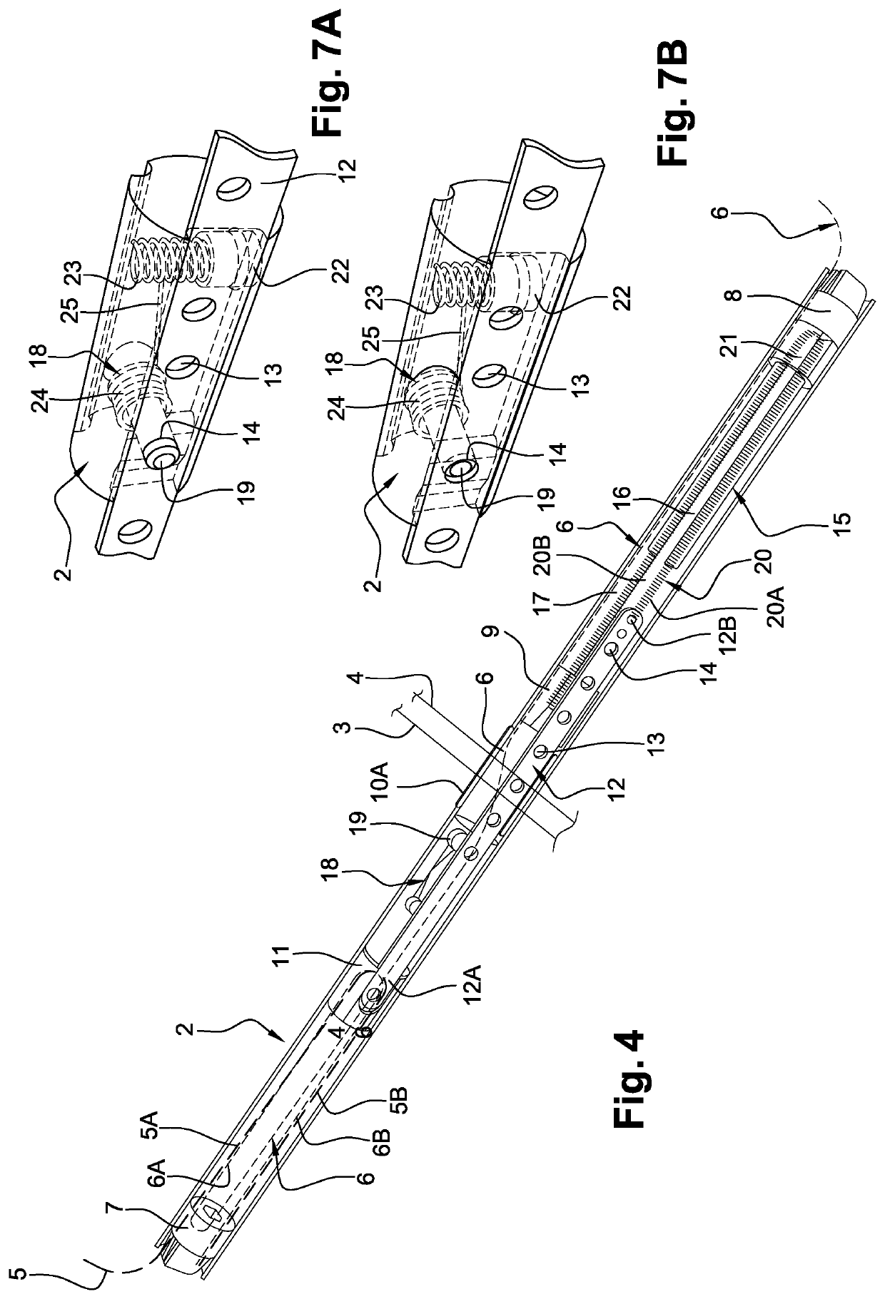
The invention is a command and control bar for traction sails that allows the user to adjust the power of the sail with ease and precision. The bar has a male lug that can lock and release the displacement of the long element, which is connected to the sail. This makes it simple for the user to hold the bar and adjust the sail's inclination. The bar is also designed to be sealed from sand, which helps to protect it from damage. Overall, this invention provides a better and more efficient way to control the power of a traction sail.

Problems solved by technology

That creates a major drawback in terms of controlling the sail, which is all the more disadvantageous because the user precisely needs to better control the bar when the wind force and / or direction changes.
Further, known mechanisms are not totally sealed, and the presence of sand affects their working and reliability.

Method used


Image

  • Command and control device for kites
  • Command and control device for kites
  • Command and control device for kites

Examples


Embodiment Construction

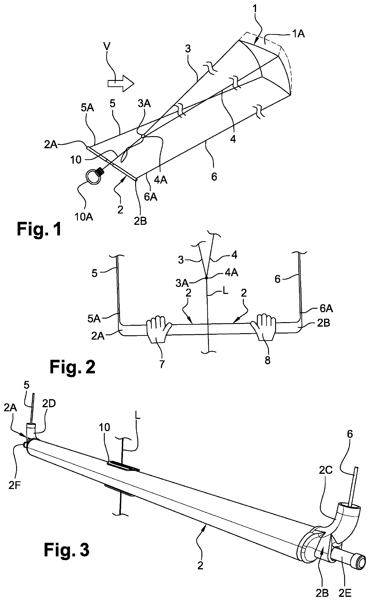
[0052]FIG. 1 is a schematic diagram of a convex sail 1 that is shaped like a parallelepiped or square, and is connected to a command bar 2, held by a user, who is not shown, through two front cables or lines 3 and 4 and two rear lines or cables 5 and 6.

[0053]The lines or cables 3, 4, 5, and 6 have one end each connected to a respective corner of the sail 1. The ends 6A and 5A, opposite the sail 1, of the rear cables 5 and 6 are connected to the ends 2A, 2B of the bar 2. The ends 3A and 4A (opposite sail 1) of the front cables 3 and 4 are connected to a common central end 10 that passes close to or at the center of the command bar 2. Beyond bar 2, opposite the sail, the end 10 protruding from the bar is connected to a handle or ring, known as the “dropping” ring 10 A.

[0054]In a known manner, depending on the wind speed and / or direction symbolized by the arrow V, the user holding the bar 2 modifies the length of the front cables 3 and 4, by example in the manner shown in FIG. 1 where ...


PUM


Abstract

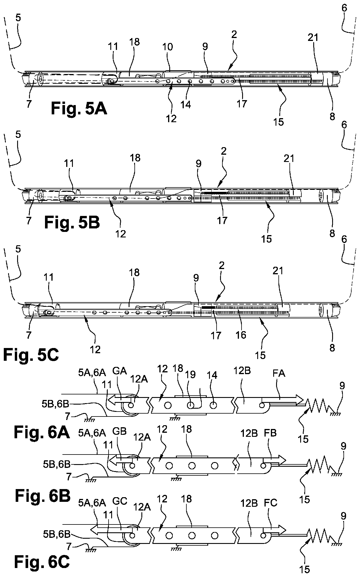
A command and control bar for a kite sail associated with two front cables connected to a user and two rear cables connected to the bar. The cables are connected at one end to the sail. An adjustment element to shorten / extend the rear cables is incorporated into the bar and can be controlled by the user without releasing the bar. A deflection system can be displaced parallel to the axis of the bar and is connected to a return element. The bar includes a locking element to lock / release the position of the deflection system along the bar, depending on the traction forces applied on the cables. The locking element is accessible to the user from outside the bar.

Description

RELATED APPLICATIONS[0001]This application claims priority from French Patent Application No. 16 56874 filed Jul. 19, 2016, which is incorporated herein by reference in its entirety.FIELD OF THE INVENTION[0002]This invention relates to an improved command and control device for a traction sail of the kite type, or for the rigging of a sailboat (integrated into the boom).[0003]The invention further relates to a kite sail or a sailboat boom for a sailboard, fitted with such a device.[0004]The invention will be described in view of its application to a kite sail, integrated into the bar of said sail, without being limited to that application.BACKGROUND OF THE INVENTION[0005]It is known that kite sails are made up of one or more soft sails, generally elliptical or semi-elliptical in shape, flat or semi-flat, where the concave side is designed to be placed in the wind to create a means of traction, and possibly movement, by a user or other, connected to the sail by cables called lines.[0...

Claims


Application Information

Patent Timeline
Patent Type & Authority Patents(United States)
IPC IPC(8): B63H8/16B63H9/00B64C31/06B63H9/10
CPCB63H8/16B63H9/00B64C31/06B63H9/10B63H9/069
Inventor CAMBLONG, MARTIALVLAMINCK, SIEGFRIED
Owner MX PRODION
Learn More