Television proximity sensor

Active Publication Date: 2006-08-29
NIELSEN COMPANY US LLC THE A DELAWARE LIMITED LIABILITY
View PDF12 Cites 69 Cited by
  • Summary
  • Abstract
  • Description
  • Claims
  • Application Information

AI Technical Summary

Benefits of technology

[0013]The processing may also include continuously updating the measurements of the first, second, and third power levels, and comparing the most recent measurement of the first power level to a predetermined second threshold value. When the first power level is greater than or equal to the second threshold

Problems solved by technology

One of the problems encountered by a portable device is to determine whether the au

Method used


Image

  • Television proximity sensor
  • Television proximity sensor
  • Television proximity sensor

Examples


Embodiment Construction

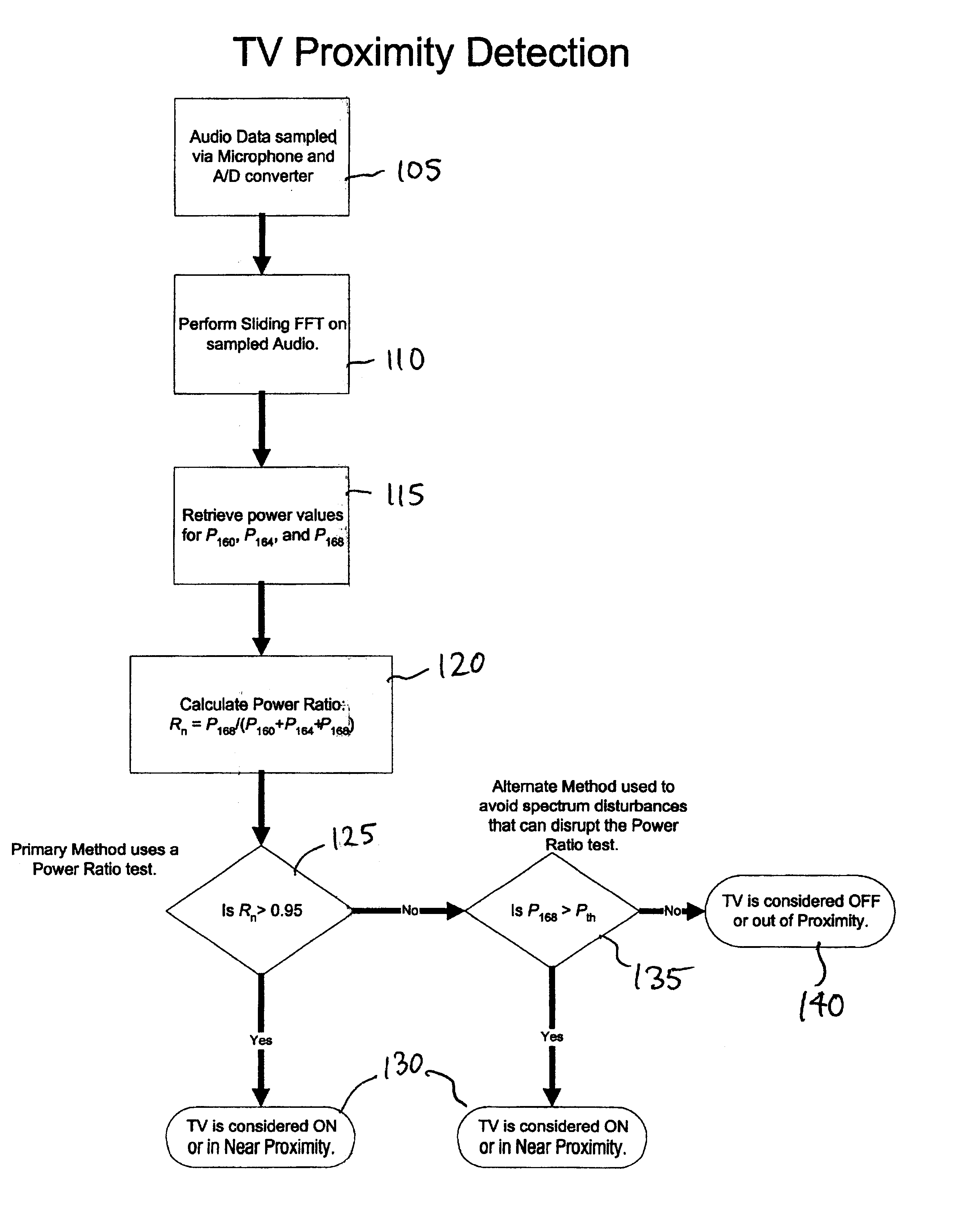
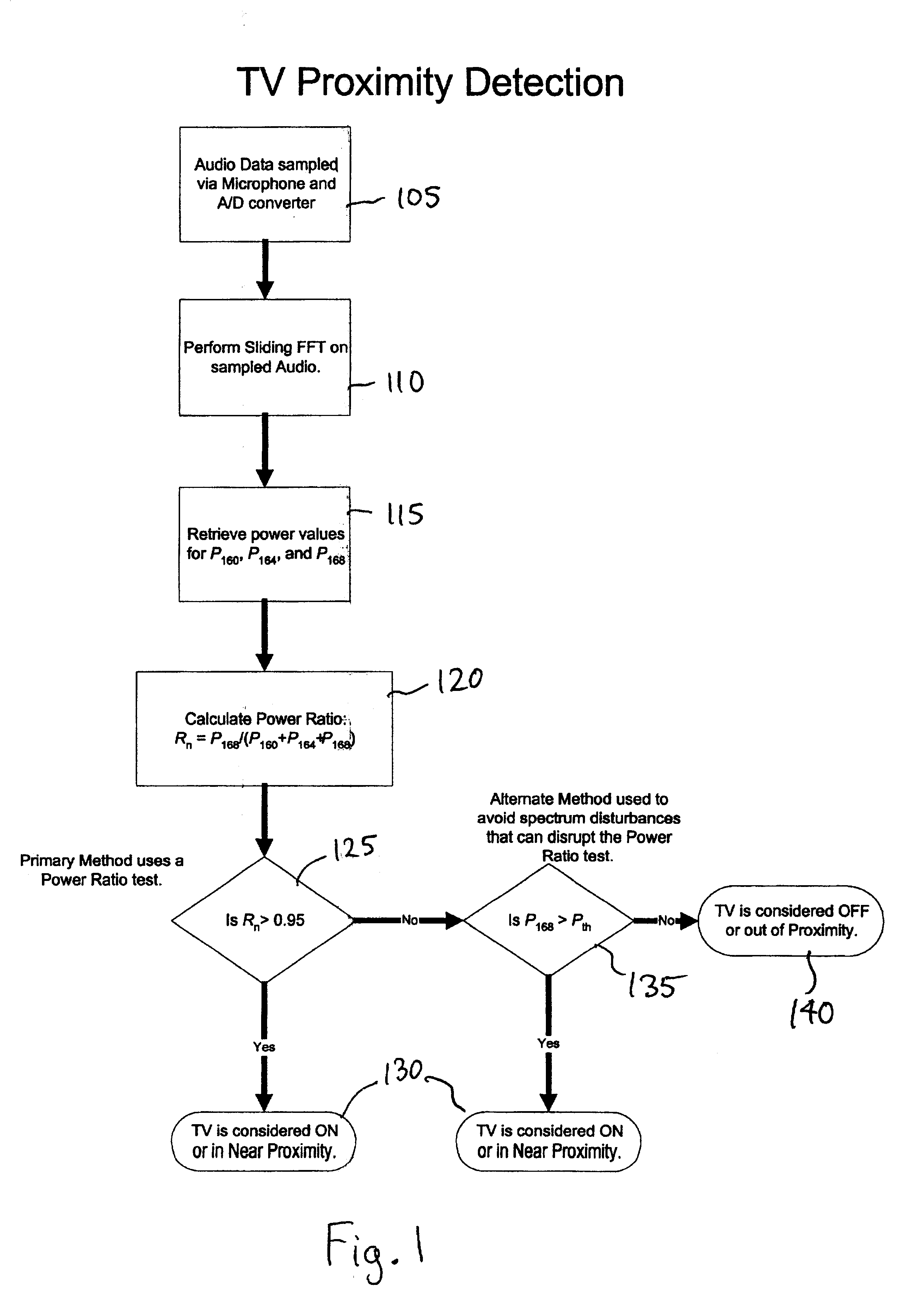
[0018]The present invention is based on the detection of a television display device property to determine whether the television is on. For example, all television sets with Cathode Ray Tube (CRT) displays contain circuitry for scanning an electron beam across the picture tube. The transformers, which generate the required voltage to perform scanning, emit a characteristic audio signal (e.g., transformer buzz). This audio signal permeates the vicinity of a television set. Vibrations of the laminations within the transformer generate the audio. In a television system operating with the NTSC standard, the horizontal scan fly-back transformers emit a 15.75 kHz wave. The presence of this characteristic frequency can be detected from the audio signal picked up by the microphone. This high frequency tone has a fixed intensity for a given television set. It typically does not penetrate through walls, and as a result, only a microphone placed in the same room as the television set can pick...


PUM


Abstract

Systems and methods for determining whether a television is on and in as near proximity are provided. An example system includes a sensor, an analog-to-digital converter, and a digital signal processor. The digital signal processor processes a set of digital audio samples detected by the sensor to determine if the sensor is in near proximity to a television in an on state.

Description

CROSS REFERENCE TO RELATED APPLICATIONS[0001]This application claims priority under 35 U.S.C. § 119(e) to U.S. provisional Application Ser. No. 60 / 313,816, entitled “Television Proximity Sensor”, filed Aug. 22, 2001, the contents of which are incorporated by reference herein.BACKGROUND OF THE INVENTION[0002]1. Field of the Invention[0003]The present invention relates to apparatus and methods for determining whether a television is on and in near proximity to a sensor, and, more particularly, to apparatus and methods for determining whether a television audience member is in the same room as a television that is turned on.[0004]2. Description of the Related Art[0005]Television audience measurement systems are based either on portable devices carried by members of the audience, or on fixed devices placed in the vicinity of a television set. In both these applications, a microphone on the device picks up an audio signal associated with a television program. The usual objective is to de...

Claims


Application Information

Patent Timeline
IPC IPC(8): H04N9/00H04N7/16H04N17/00H04H1/00H04H60/32H04H60/52H04H60/56
CPCH04H60/32H04H60/56H04H60/52
Inventor SRINIVASAN, VENUGOPALPEIFFER, JOHN C.NELSON, DANIEL
Owner NIELSEN COMPANY US LLC THE A DELAWARE LIMITED LIABILITY
Why Eureka
Try Eureka