Snap on protective members for bed frames

a technology for protecting members and bed frames, applied in the field of bed frames, can solve the problems of presenting a particular pleasing appearance, affecting the appearance of the bed frame, and the possibility of damaging walls, other furniture and the like, and achieve the effect of convenient and convenient affixed to the componen

Inactive Publication Date: 2006-09-05
FINGER LAKES INTPROP
View PDF5 Cites 13 Cited by
  • Summary
  • Abstract
  • Description
  • Claims
  • Application Information

AI Technical Summary

Benefits of technology

[0011]Now, in accordance with the present invention, there is provided a snap on protective member that can easily and readily be affixed to a component of a bed frame such as a side rail or a center rail by simply snapping the protective member to that component. The snap on protective member comprises an elongated member, preferably of an extruded plastic material, and which can be affixed to a side rail or a center rail by means of having outer edges formed in the configuration of curved lips that, when assembled, extend around the outer edges of the bed frame components and also have projections formed in the elongated members adjacent or near the curved lips such that the protective members can be snapped to the bed frame components by sandwiching the outer edges of the components between the curved lips and the projections. The distance between the curved lips as they contact the bed frame component and the projections are dimensioned so as to hold those outer edges of the bed frame components therebetween so as to retain the protective members to the particular component.

Problems solved by technology

One of the difficulties with such bed frame construction is, however, that the exterior surface that is the visible to the user and other persons is simply the exterior vertical leg of the side rails and that does not present a particular pleasing appearance.
In addition to the appearance, there are generally sharp edges on that external vertical leg and which can be encountered by the shins or legs of the persons and cause injury and even the flat vertical surfaces themselves of the side rails are hazardous, being comprised of iron, and therefore very unforgiving if encountered or struck by a person.
In addition, since these side rails are of an iron material having sharp edges, there is a danger to inanimate objects, such as when moving the bed frame of a completed bed, there is always a possibility of damaging walls, other furniture and the like by running the bed frame into such objects.
Lastly, with the aforedescribed sharp edges, there is a distinct likelihood of tearing the material used in the box spring when the box spring is added to the bed frame or removed therefrom.
The particular protective member of Feld, however, requires a cushion material having a certain predetermined cross section all along the length of the side rail and is a fairly difficult component to produce with the necessary tolerances, particularly with the protective member constructed of the resilient material having varying thickness and its assembly to the particular bed frame component would not be particularly secure.
In addition, the use of a resilient, relatively thick material requires a considerable amount of material in making up the protective member of Feld.
There is a further problem, however, with respect to the center rail.
Thus, there is a concern by the user that the box spring will be bowed or in some way damaged by being supported by surfaces that are separated by that distance.
The result is, obviously, that there is a slight downward bow to the box spring as it sits on the cross members and the center rail separated by a fairly significant distance and which bowing is not conducive to the integrity and support of the box spring and can cause damage to that box spring.

Method used


Image

  • Snap on protective members for bed frames
  • Snap on protective members for bed frames
  • Snap on protective members for bed frames

Examples


Embodiment Construction

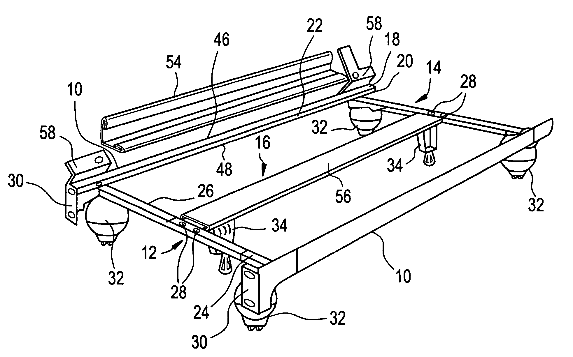
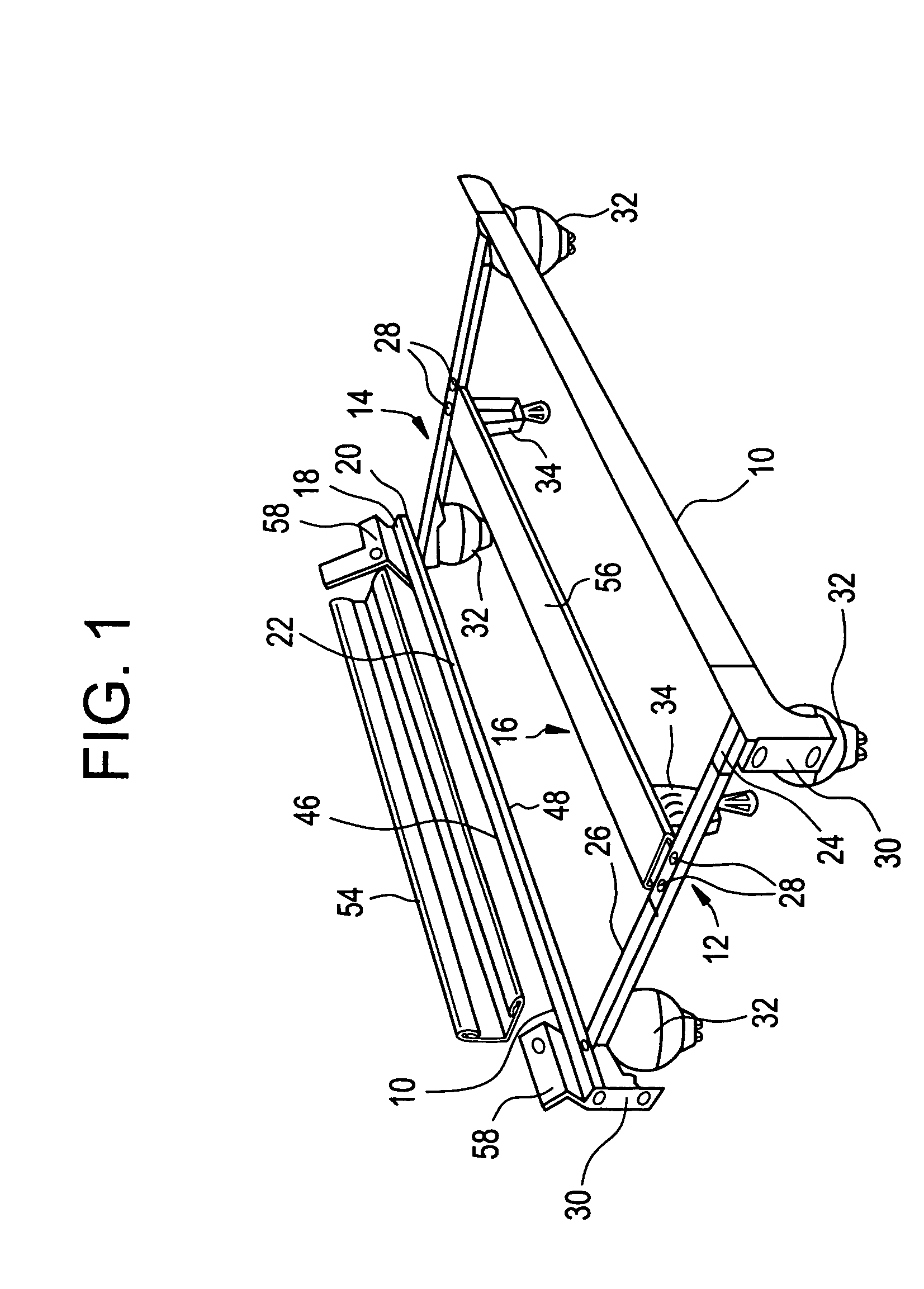
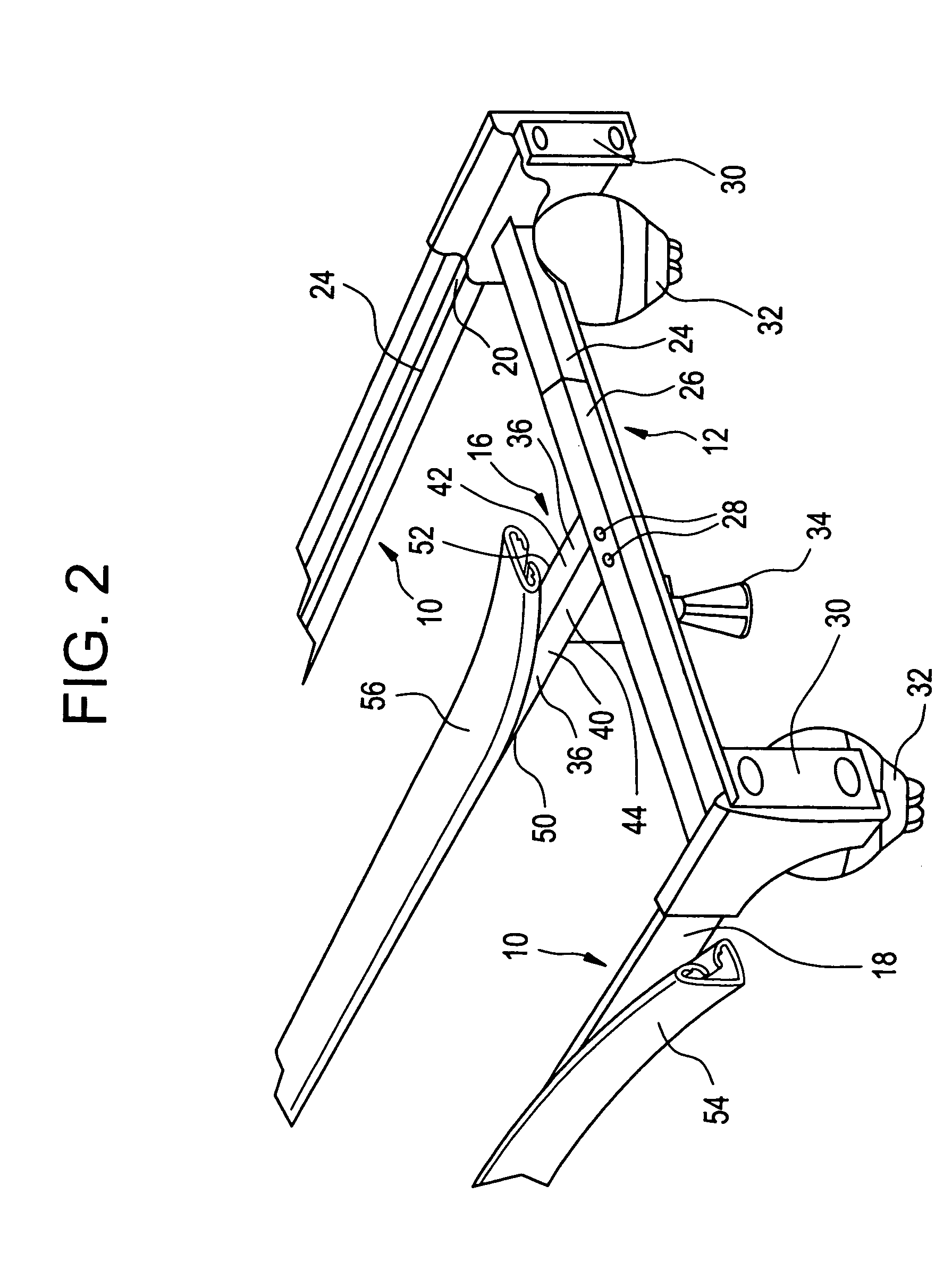
[0020]Referring now to FIGS. 1 and 2, there are shown, a perspective view of an assembled bed frame having protective members affixed thereto in accordance with the present invention and an enlarged perspective view of the head end of the bed frame with the protective members partially removed from their installed condition. Accordingly, there are a pair of side rails 10, a head cross member 12 and a foot cross member 14. In addition, there is shown a center rail 16 that extends between and is affixed to the head cross member 12 and the foot cross member 14. In the construction of the bed frame, the side rails 10 are provided in the configuration of L-shaped angle irons having a vertical leg 18 along the exterior of the bed frame and with a horizontal leg 20 extending inwardly therefrom and, as will be seen, the horizontal leg 20 provides an upper surface 22 upon which rests a box spring when an eventual bed is assembled for use.

[0021]The head cross member 12 and the foot cross memb...


PUM


Abstract

A protective member, preferably an extruded plastic is used to enclose, at least partially, a component of a bed frame so as to provide protection against inadvertent injury to a user striking the otherwise sharp edges of the component. The components are normally a side rail and a center rail and the protective member is snapped fitted to that component by the presence of curved lips that at least partially encircle the external edges of the component. There are also ribs formed in the protective member and which position the protective member a predetermined distance away from the particular component. In the case of the center rail, the protective member is spaced away from the upper surface of the center rail so as to compensate for the lower position of that surface with respect to the head and foot cross members so that a box spring resting upon the side rails and the center rail is supported evenly and does not bow at its center due to a spatial difference between the center rail and the cross members.

Description

[0001]This application is a continuation of Ser. No. 09 / 997,389 abondened Nov. 29, 2001.BACKGROUND OF THE INVENTION[0002]The present invention relates to a bed frames, and, more particularly, to protective members that can be readily assembled to certain components of a bed frame.[0003]In general, bed frames are comprised of a pair of side rails and a plurality of cross members that span between the side rails in order to assembly and complete the bed frame structure. The side rails are normally L-shaped angle irons that have a vertical leg forming the exterior of the bed frame and a horizontal leg that extends inwardly with respect to the bed frame at the lower extremity of the vertical leg. In addition, there is also normally a center rail affixed to the cross members and which parallels the two side rails and is generally centered between those side rails. The center rail can be made up of two L-shaped angle irons that are attached together back to back such that there is a doubl...

Claims


Application Information

Patent Timeline
Patent Type & Authority Patents(United States)
IPC IPC(8): A47C21/00A47C19/02
CPCA47C19/024A47C19/021
Inventor POLEVOY, RICHARD S.RYAN, HOWARD SCOTTCARLSON, PAUL ERIC
Owner FINGER LAKES INTPROP
Why Eureka
Try Eureka