Surface profile measuring instrument and surface profile measuring method

a technology of surface profile and measuring instrument, which is applied in the direction of measuring devices, instruments, electric/magnetic measuring arrangements, etc., can solve the problems of change in sensitivity characteristics, inability to obtain the surface profile of such workpieces, and inability to correctly determine the contact position.

Active Publication Date: 2006-09-05
MITUTOYO CORP
View PDF6 Cites 22 Cited by
  • Summary
  • Abstract
  • Description
  • Claims
  • Application Information

AI Technical Summary

Benefits of technology

[0038]An object of the present invention is to provide a surface profile measuring instrument and profile measuring method capable of overcoming the above disadvantages and correctly measuring a surface profile of a workpiece.

Problems solved by technology

Further, even when the sensitivity characteristics does not change, when the contact point between the contact portion 22 and the workpiece W is not located in the direction of the correction vector, the contact position cannot be correctly obtained, so that the surface profile of such workpiece also cannot be obtained.
Such problem also occurs when surface profile of a workpiece is measured with a non-contact probe.
This is because, when the sensor head is not in normal opposing condition relative to the workpiece surface, electrostatic capacitance between the portion around the tip end of the sensor head and the measurement surface is not uniformly distributed, which results in the change in the sensitivity characteristics, so that the distance gap cannot be correctly measured.
In other words, when such non-contact probe is used in a scanning measurement where the workpiece surface may not be constantly in normal-opposing condition relative to the sensor head, the surface profile of the workpiece may not be correctly measured.

Method used


Image

  • Surface profile measuring instrument and surface profile measuring method
  • Surface profile measuring instrument and surface profile measuring method
  • Surface profile measuring instrument and surface profile measuring method

Examples


first embodiment

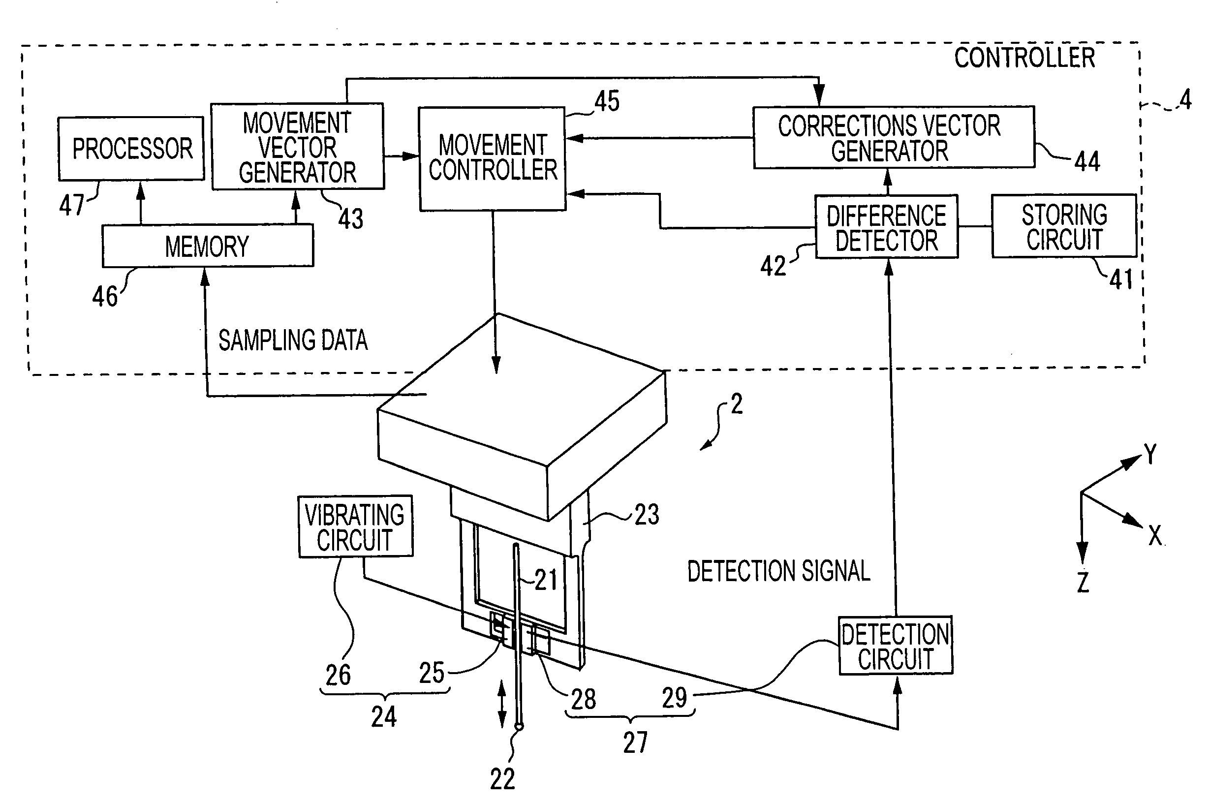
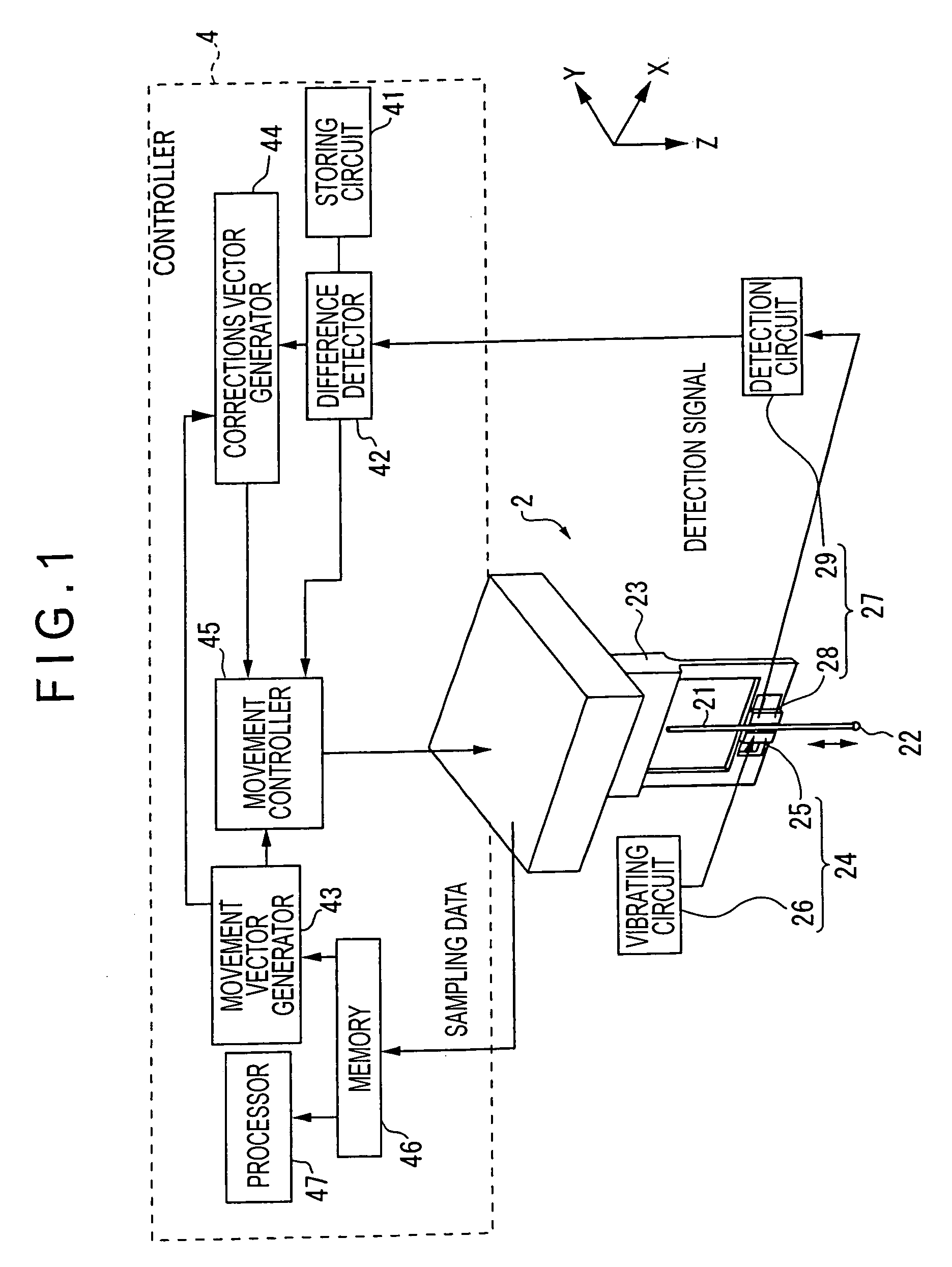
[0107]A first embodiment of a surface profile measuring instrument according to the present invention has approximately the same arrangement as the surface profile measuring instrument 1 shown in FIG. 14 described in the Related Art section except for the characteristic feature in the controller 4.

[0108]As shown in FIG. 14, the surface profile measuring instrument 1 has a contact probe 2 having a contact portion 22 to be in contact with the surface of a workpiece W, a drive mechanism 3 for moving the contact probe 2 relative to the workpiece W, and a controller 4 for controlling the drive mechanism 3.

[0109]For the convenience of describing the present invention, Z-axis is set in the axial direction of the stylus 21 (downward in FIG. 14), and X-Y plane is set orthogonal with the Z-axis.

[0110]The contact probe 2 may be the same as the probe described in the Related Art section.

[0111]The contact probe 2 has a stylus 21 having the contact portion 22 at the tip end thereof, a stylus hold...


PUM


Abstract

A surface profile measuring instrument for measuring a surface profile of a workpiece has: a probe having a stylus provided with a measuring portion for measuring a surface of a workpiece at a tip end thereof and a detector for outputting a detection signal which varies depending on a measurement condition between the surface of the workpiece and the measuring portion; a scanning mechanism for relatively moving the measuring portion along the surface of the workpiece; a memory (46) that stores a position information of the contact portion when the detection signal reaches a predetermined reference signal value; a vibration inclination angle calculator (51) that calculates a response variation factor (vibration inclination angle θ) that applies variation to the detection signal from the surface of the workpiece; and a profile processor (53) that corrects the position information to obtain an actual profile of the surface of the workpiece using the response variation factor.

Description

BACKGROUND OF THE INVENTION[0001]1. Field of the Invention[0002]The present invention relates to a surface profile measuring instrument and a surface profile measuring method. Specifically, it relates to a surface profile measuring instrument and surface profile measuring method for continuously autonomic-measuring a surface profile of a workpiece by scanning and profiling the surface of the workpiece by a probe.[0003]2. Description of Related Art[0004]A surface profile measuring instrument that measures a profile of a surface of a workpiece with a contact probe attached to a coordinates measuring machine has been known, the instrument continuously measuring the surface profile of a workpiece by scanning and profiling the surface of a workpiece with a tip end of a stylus.[0005]As shown in FIG. 14, a conventional surface profile measuring instrument 1 has a contact probe 2 having a contact portion 22 to be in contact with a surface of a workpiece W, a drive mechanism 3 for moving the...

Claims


Application Information

Patent Timeline
Patent Type & Authority Patents(United States)
IPC IPC(8): G01B5/20G01B5/28G01B21/20G01B7/28G01B21/30
CPCG01B5/28G01B21/30G01B7/28
Inventor MATSUKI, KAORUHIDAKA, KAZUHIKO
Owner MITUTOYO CORP
Why Eureka
Try Eureka