Nail holder

a nail holder and nail technology, applied in the field of nail holder, can solve the problems of less than desirable visibility of known devices and unfavorable nail positioning, and achieve the effect of improving the nail holder and accurately defining the nail orientation

Inactive Publication Date: 2006-09-05
RUFOLO JR JOSEPH
View PDF20 Cites 27 Cited by
  • Summary
  • Abstract
  • Description
  • Claims
  • Application Information

AI Technical Summary

Benefits of technology

[0019]By employing the foregoing principles an improved nail holder is achieved. In one preferred embodiment the nail holder has an ergonomically curved handle with a distal working head having an upper bifurcated cantilever and a lower embedded magnet. Preferably, the magnet is spaced from the bifurcated cantilever to capture the nail and establish a desired alignment when the nail is embraced by the bifurcation. Also, this preferred nail holder has at its working head a flat bottom that can be flatly rested on a work surface to establish an accurately defined nail orientation. A rounded corner next to the flat bottom can be used to tilt the nail when the user wishes to establish a different angular orientation.
[0020]In another preferred embodiment, the working head can be pivotally attached to the handle so the user can adjust the angle of the working head and use the handle at an angular orientation satisfying the user's preferences. In such embodiments tilting of the working head can be avoided by extending its flat bottom fore and aft so the flat bottom lies flatly against a work surface when the user presses down.

Problems solved by technology

Nevertheless, the known devices have less than desirable visibility and have not been well arranged to facilitate capturing the nail and holding it in a desired orientation at a work surface.

Method used


Image

  • Nail holder
  • Nail holder
  • Nail holder

Examples


Embodiment Construction

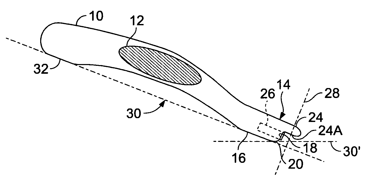
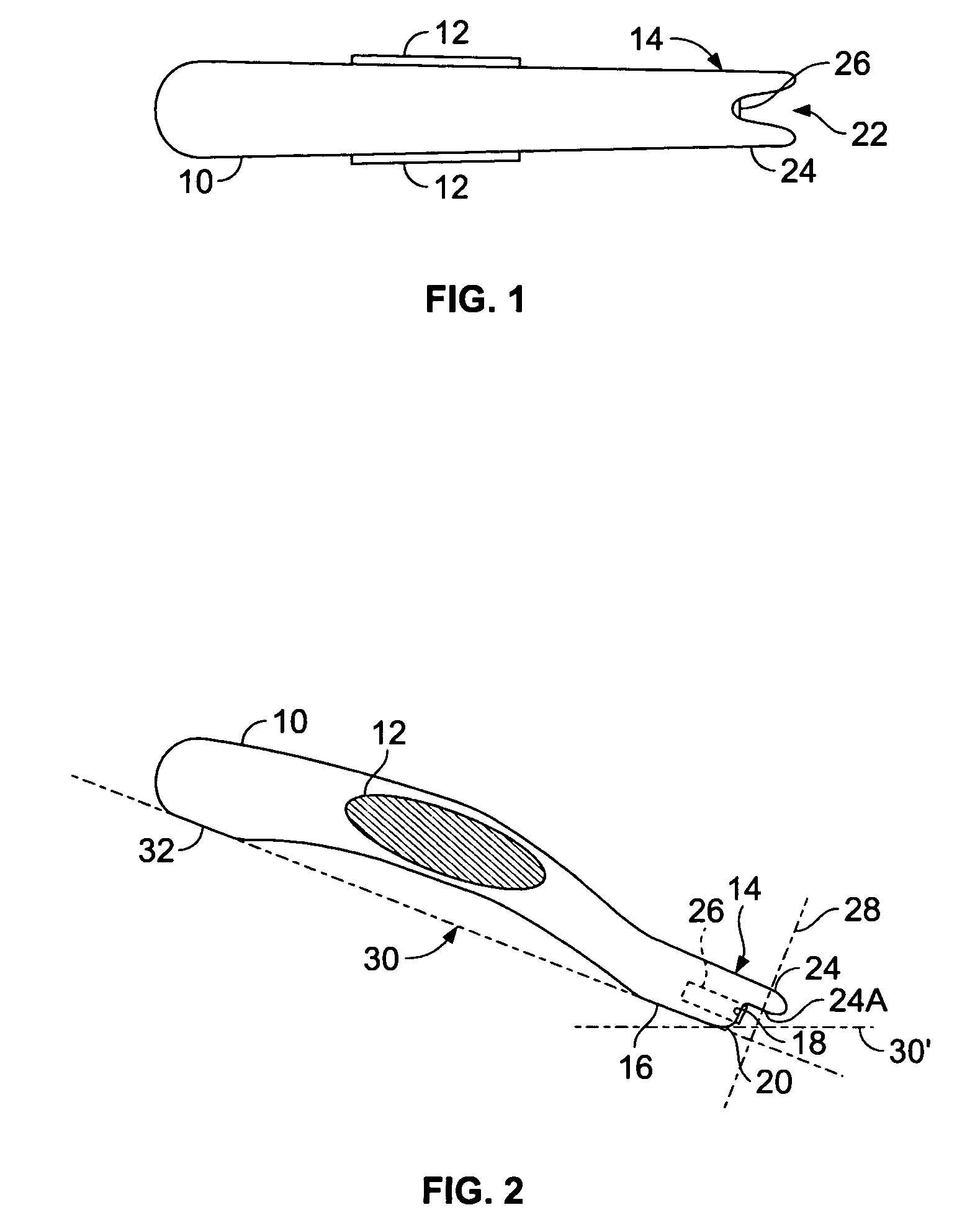
[0038]Referring to FIGS. 1 and 2 an example of a nail holder is shown with an arched, ergonomically shaped handle 10 that has a slight taper from the proximal to distal ends. In this embodiment the overall length of the nail holder is 6 inches, and preferably this dimension is 4 to 10 inches. A knurled pair of oval, external finger pads 12 are embossed near the center of the right and left sides of handle 10. The distal end of handle 10 is formed into a working head 14 having a flat bottom 16 that meets the transverse distal face 18 in a rounded corner 20.

[0039]Working head 14 supports an integral cantilever 24 having a V-shaped bifurcation 22 with a rounded root. The underside 24A of cantilever 24 overhangs and is approximately perpendicular to the distal face 18 of working head 14.

[0040]Embedded in working head 14 is a magnetic element 26 whose distal pole extends slightly beyond distal face 18. Element 26 is a permanent magnet strong enough to securely hold a nail (shown hereinaf...


PUM


Abstract

A nail holder includes a handle having a working head with a cantilever that is bifurcated and sized to receive a nail. The nail holder also includes a magnetic element mounted at the working head.

Description

BACKGROUND OF THE INVENTION[0001]1. Field of the Invention[0002]The present invention relates to nail holders, and in particular to holders including a magnetic device at a bifurcated distal end.[0003]2. Description of Related Art[0004]Holding a nail with a holding device instead of by hand makes visually locating the nail tip easier and reduces the risk of injury during hammering. Nevertheless, the known devices have less than desirable visibility and have not been well arranged to facilitate capturing the nail and holding it in a desired orientation at a work surface.[0005]In FIG. 2 of U.S. Pat. No. 4,967,623 magnetic head 7 has a slot for holding a nail. FIGS. 3 and 5 show a hand tool with a magnetic head 13 having a slot for holding a nail. In the embodiment of FIG. 6 the magnetic head is replaced with a V-shaped magnetic plate.[0006]In U.S. Pat. No. 3,060,442 both ends of a flexible nail holder are bifurcated and have recesses 20, 21, 32, and 33 for holding a nail.[0007]U.S. De...

Claims


Application Information

Patent Timeline
Patent Type & Authority Patents(United States)
IPC IPC(8): B25C3/00
CPCB25G1/06B25C3/008
Inventor RUFOLO, JR., JOSEPH
Owner RUFOLO JR JOSEPH
Why Eureka
Try Eureka