Decorative display flag for rotatable attachment to movable poles for residential and commercial uses

a technology of decorative display and movable poles, which is applied in the direction of flags/banners, display means, instruments, etc., can solve the problems of difficult and cumbersome assembly and disassembly of mechanical connectors, permanent secured poles are difficult to remove from set locations, and cannot be easily moved

Inactive Publication Date: 2006-09-05
MARKERS
View PDF14 Cites 10 Cited by
  • Summary
  • Abstract
  • Description
  • Claims
  • Application Information

AI Technical Summary

Problems solved by technology

Intervening mechanical connectors are difficult and cumbersome to assemble and disassemble necessitating existing poles to be retrofitted with connectors to hang a flag on a pole.
Permanently secured poles are difficult to remove from set locations and cannot be easily moved to change location of the flag pole or flag poles or rearrange multiple poles to change the overall flag display.
Flags not securely tied or knotted to the pole can fall off due to the ties loosening.
Although interior flags are not subjected to outside weather or wind, such flags ordinarily were permanently fixed to a pole thereby preventing easy detachment and interchangeability of multiple flags depending on the season or occasion.

Method used


Image

  • Decorative display flag for rotatable attachment to movable poles for residential and commercial uses
  • Decorative display flag for rotatable attachment to movable poles for residential and commercial uses
  • Decorative display flag for rotatable attachment to movable poles for residential and commercial uses

Examples


Embodiment Construction

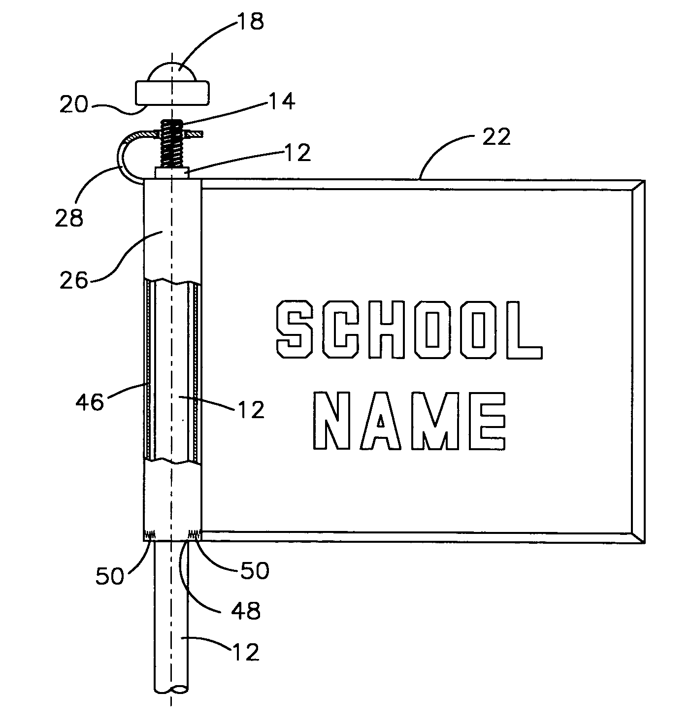
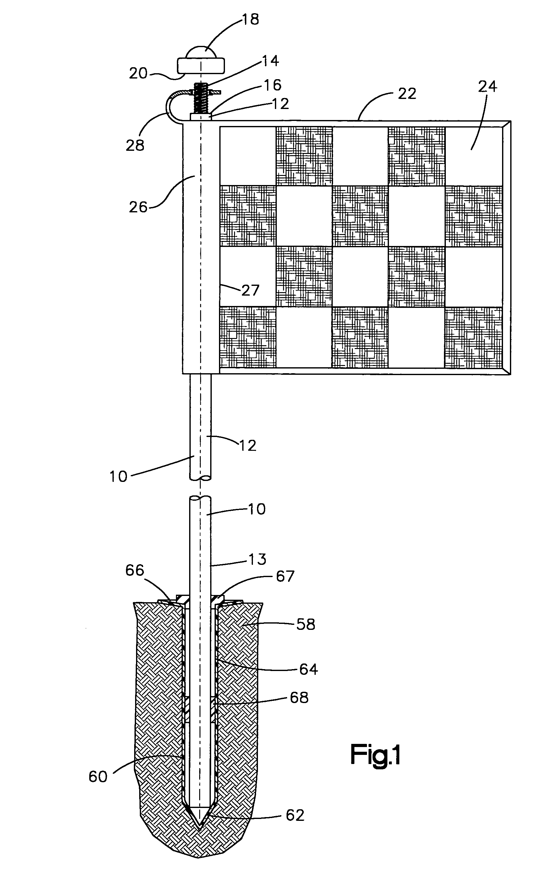
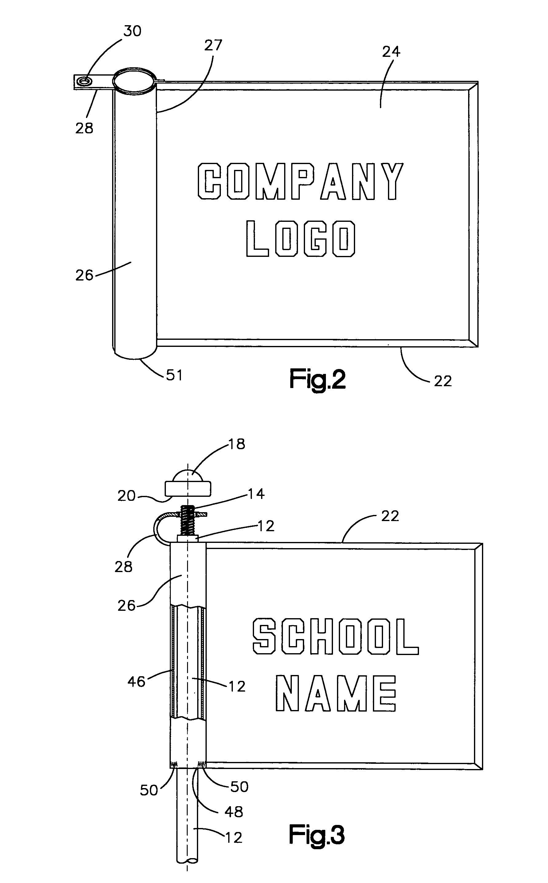
[0012]Referring now to the drawings wherein like reference numbers designate like parts, shown in FIG. 1 is a preferred embodiment of this invention showing a flag pole 10 with an exterior decorative flag 22 attached to the pole 10 in accordance with this invention. The flag pole 10 comprises an upper pole section 12 terminated at the top end with an upwardly extending smaller diameter pin or threaded screw 14. The juncture of the larger diameter pole 12 and the reduced diameter threaded pin or screw 14 forms an intervening laterally disposed peripheral shoulder 16. The upright threaded screw 14 is adapted to engage a threaded capping nut 18 having a lower edge 20 and internal threads with a threaded depth of about one-half of the vertical length of threaded screw 14 to leave vertical spacing of about one-half the vertical length of the screw 14 between the lower edge 20 of the capping nut 18 and the peripheral shoulder 16 when the capping nut 18 is tightened downwardly onto the upr...


PUM


Abstract

A decorative residential or commercial flag for attachment to a supporting upright pole having flag attachment means comprising a linear sleeve adapted to loosely slip over the upright pole to enable unobstructed rotation of the flag in response to wind direction along with a flexible tab secured to the top of the linear sleeve adapted to rotatably engage an upwardly extending narrow pin located at the top of the upright pole. The flexible tab contains an opening larger than the narrowed upright extension to enable free rotation of the tab around the narrowed extension, while the opening is smaller than the upright pole to enable the larger diameter pole to vertically support the flexible tab. The flexible tab supports the decorative flag vertically on the upright pole while the sleeve enables circumferential rotation of the decorative flag about the axis of the upright pole. The decorative flag can be attached directly to an upright pole or inclined pole. Preferred flags are outdoors flags supported vertically by inserting the bottom end of the pole into a ground socket sunk into the ground flush with the ground, which permits expedient installation of the flag pole and easy removal of the pole for storage or rearrangement if desired. Alternatively the flagpole can be supported by a weighted holder resting on interior furniture or floors, or outside on a patio or other flat surface.

Description

RELATED PATENT INFORMATION[0001]This application is a Continuation-in-Part Application of U.S. patent application Ser. No. 10 / 674,708, filed Sep. 30, 2003 now U.S. Pat. No. 7,062,873, for a “GOLF MARKING FLAG FOR ATTACHMENT TO MOVABLE POLES FOR MARKING HOLE LOCATION IN GOLF COURSE GREENS”.FIELD OF THE INVENTION[0002]This invention pertains to decorative display flags on movable poles for exterior or interior use on residential and commercial properties to display decorative colors graphics, numbers, lettering, or similar display.BACKGROUND OF THE INVENTION[0003]Residential dwellers as well as commercial properties frequently like to display colorful decorative flags to attract attention or provide informative to the public. Such flags can be multiple color whimsical design of random or a set pattern of colors, graphics, numbers, lettering or similar design identifying school or organization affiliation or advertising brand name colors or company colors and products, union or club af...

Claims


Application Information

Patent Timeline
Patent Type & Authority Patents(United States)
IPC IPC(8): G09F17/00
CPCA63B57/0056G09F17/00A63B2210/50A63B57/357A63B57/40
Inventor HLAVIN, DALE J.
Owner MARKERS
Why Eureka
Try Eureka