Lead guide for cable extension type position sensors

a technology of lead guide and position sensor, which is applied in the field of position related sensors, can solve the problems of limited sensing distance of winding cable type position sensor, affecting the accuracy of position sensor, etc., and achieves the effect of minimizing surface abrasion, full accuracy, and expanding the range of cable extension type sensors

Inactive Publication Date: 2006-09-05
CONTROL PRODS
View PDF49 Cites 8 Cited by
  • Summary
  • Abstract
  • Description
  • Claims
  • Application Information

AI Technical Summary

Benefits of technology

[0010]The present invention allows a significantly greater number of turns to be wound onto a cable spool, without the cable coiling over itself. This substantially extends the range of cable extension type sensors, while maintaining full accuracy.
[0011]The position sensor of the present invention includes a rotatable spool around which the cable is coiled in a plurality of individual windings. A distal end of the cable is affixed to the object desired to be sensed and the rotational position of the spool is then detected as the object moves toward and away from the spool, thereby winding and unwinding the cable and causing the spool to rotate in a direct correlation to the position of the object with respect to the spool.
[0012]With the present invention, however, the spool is located within or adjacent to a guide that is provided as a fixed structure or frame for the spool and that guide has an elongated slot formed therein through which the cable passes as it winds and unwinds about the spool. The advantage of the elongated slot design depends upon the fact that the cable can follow the winding as it progresses across the spool. In this way, the point at which the cable is fed through the guide is never too far from the point at which the latest winding is forming. There is no tendency for the cable to wind over itself.
[0013]In addition, the main axis of the elongated slot can be at an angle with respect to the main rotational axis of the spool, and preferably at a preferred range of angles, such that additional advantages are realized. As one such advantage, the use of an angular orientation of the slot with respect to the spool creates a winding bias that causes the cable to always start at one side of the spool and wind in neat, consecutive rows of windings toward the other side of the spool. In the preferred embodiment, the elongated slot is a closed configuration.
[0014]As further features of the present invention, the guide itself can be constructed to provide a predictable starting point for the cable winding upon the spool; the guide can be formed so as to minimize surface abrasion as the cable passes thorough the elongated slot formed in the guide and the configuration of the guide can be designed to control the radius of any bends that the cable must undergo in the winding and unwinding of the cable about the spool.

Problems solved by technology

Accordingly, one of the difficulties with the aforedescribed type of position sensor is to have some system or mechanical function that provides a easy means to direct the cable to wind and unwind about the spool in an orderly fashion so that the winding function creates an even coiling of the cable without overlapping of any of the individual windings that make up the aggregate cable coil.
The overlapping of individual windings of the cable coil has a deleterious effect on the accuracy of the position sensor.
In this way, the winding cable type of position sensor may be limited in sensing distance by the number of consecutive winds that can be made without the overlapping of individual windings of the cable coil.

Method used


Image

  • Lead guide for cable extension type position sensors
  • Lead guide for cable extension type position sensors
  • Lead guide for cable extension type position sensors

Examples


Embodiment Construction

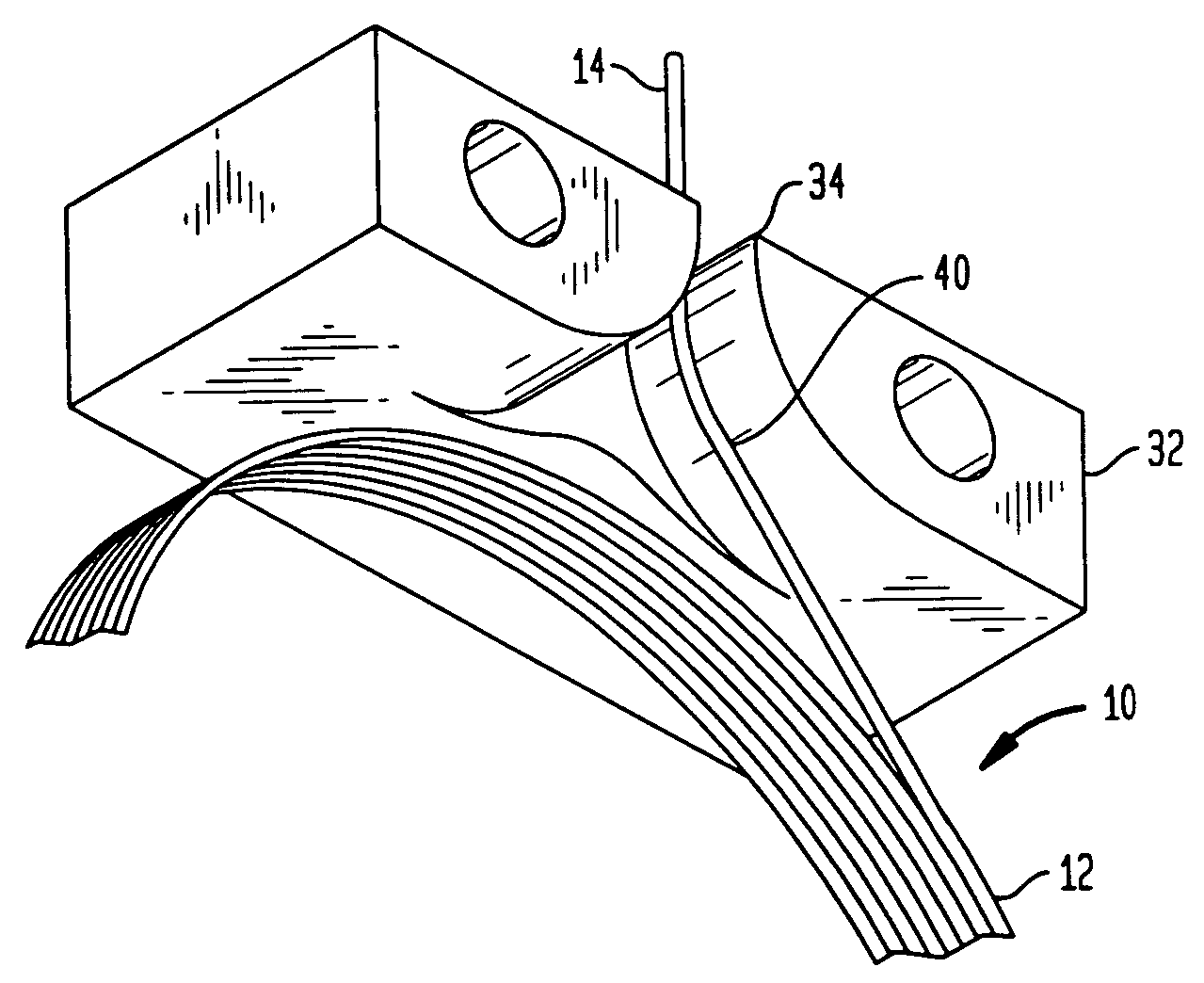
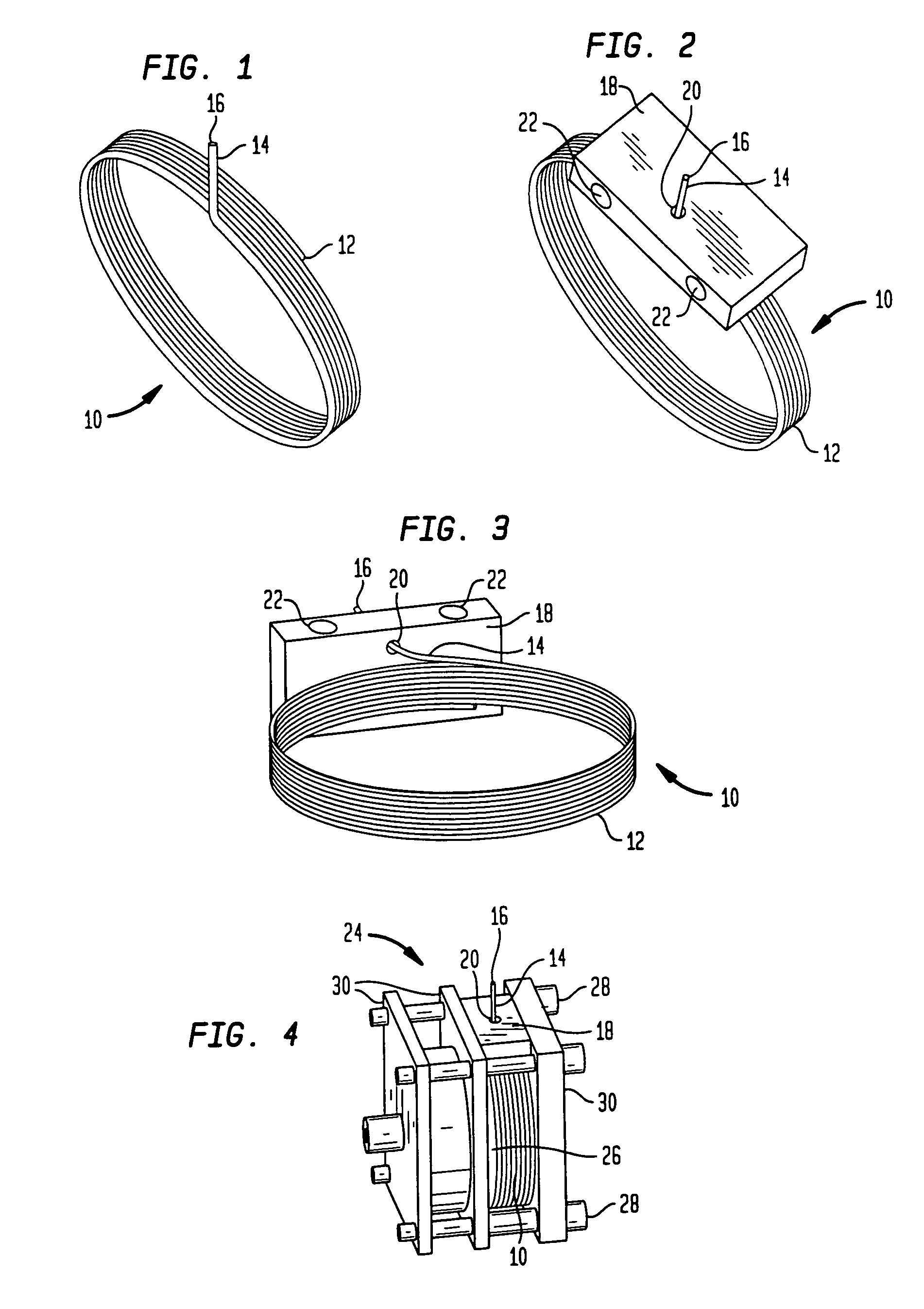
[0025]In FIG. 1, there is shown a perspective view of a cable coil 10 that comprises a plurality of individual windings 12 of cable 14 and showing a free end 16 that extends from the cable coil 10 and, in accordance with the aforementioned U.S. Pat. No. 6,234,061 is adapted to be affixed to the particular object whose position is desired to be sensed. As can therefore be seen, the cable coil 10 is typical of a coil of cable that is normally wrapped around a spool of a position sensor in accordance with that patent, however, for clarity in describing the present invention, the spool has not been shown in FIG. 1.

[0026]Accordingly, as shown, the free end 16 of the cable 14 is adapted to be affixed to the particular object whose position is desired to be determined and as that object moves toward and away from the cable coil 10, the cable coil 10 will add or subtract individual windings 12 while the spool rotates. That rotation of the spool is, in accordance with the teaching of the afo...


PUM


Abstract

A position sensor and sensor assembly having a spool onto which is wound a plurality of individual windings to make up a cable coil. A free end of the cable extends through a guide for attachment to an object whose position is desired to be sensed. The cable passes through an elongated slot formed the guide and which is preferably formed at a predetermined angle with respect to the central axis of rotation of the spool. By means of the elongated slot, the individual windings can be wound about the spool without successive windings overlapping each other. The elongated slot further has an internal surface that has a minimum radius to prevent the cable from making too small a bend during the winding function.

Description

RELATED APPLICATIONS[0001]This application is a Continuation of Ser. No. 10 / 350,292, filed on Jan. 23, 2003 now abandoned, which is based upon and claims the benefits of U.S. Provisional Patent Application 60 / 351,007, filed on Jan. 23, 2002.FIELD OF THE INVENTION[0002]The invention generally relates to position related sensors, and more particularly to a system to wind a cable about a spool in a position related sensor.BACKGROUND[0003]There are, of course, many different types of position related sensors, that is, sensors that sense the position of some physical object and provide information as to the location of that object. One such sensor is shown and described in pending U.S. patent application Ser. No. 09 / 793,218 entitled “PRECISION SENSOR FOR A HYDRAULIC CYLINDER” and which, in turn, is a continuation-in-part of U.S. Pat. No. 6,234,061, issued on May 22, 2001, entitled “PRECISION SENSOR FOR A HYDRAULIC CYLINDER” and which was based upon U.S. Provisional application 60 / 104,866...

Claims


Application Information

Patent Timeline
Patent Type & Authority Patents(United States)
IPC IPC(8): B65H75/34B65H75/38G01B21/02
CPCG01B21/02
Inventor GLASSON, RICHARD
Owner CONTROL PRODS
Why Eureka
Try Eureka