Manual electric generating device

a technology of electric generating device and manual, which is applied in the direction of instruments, sports apparatus, gymnastics exercise, etc., can solve the problem of not being able to output power supply to other portable electronic devices for their us

Inactive Publication Date: 2006-09-05
SHEN KUN TSAI
View PDF31 Cites 25 Cited by
  • Summary
  • Abstract
  • Description
  • Claims
  • Application Information

AI Technical Summary

Benefits of technology

[0004]The primary objective of the present invention is to provide a manual electric generating device, more particularly a manual electric device that can provide power to light up a luminescent member and also supply power to charging a portable electronic device or using its indicating lamp, in addition to training the user's wrist.
[0006]To make it easier for our examiner to understand the objective of the invention, its structure, innovative features, and performance, we use a preferred embodiment together with the attached drawings for the detailed description of the invention.

Problems solved by technology

However, the foregoing wrist trainer during its rotation can produce power supply to light up the luminescent members, but it cannot output power supply to other portable electronic devices for their use, which is definitely a deficiency.

Method used


Image

  • Manual electric generating device
  • Manual electric generating device
  • Manual electric generating device

Examples


Embodiment Construction

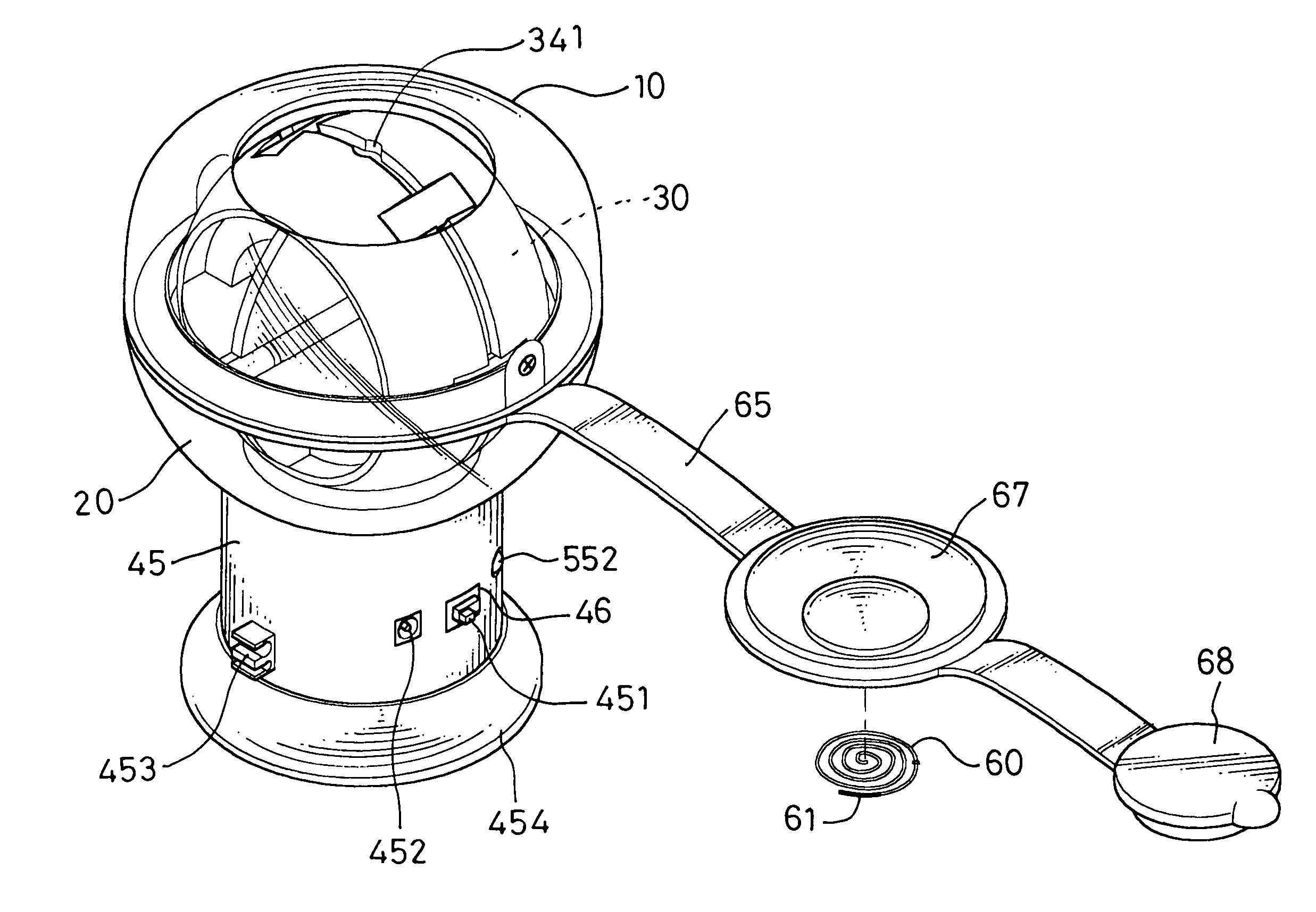
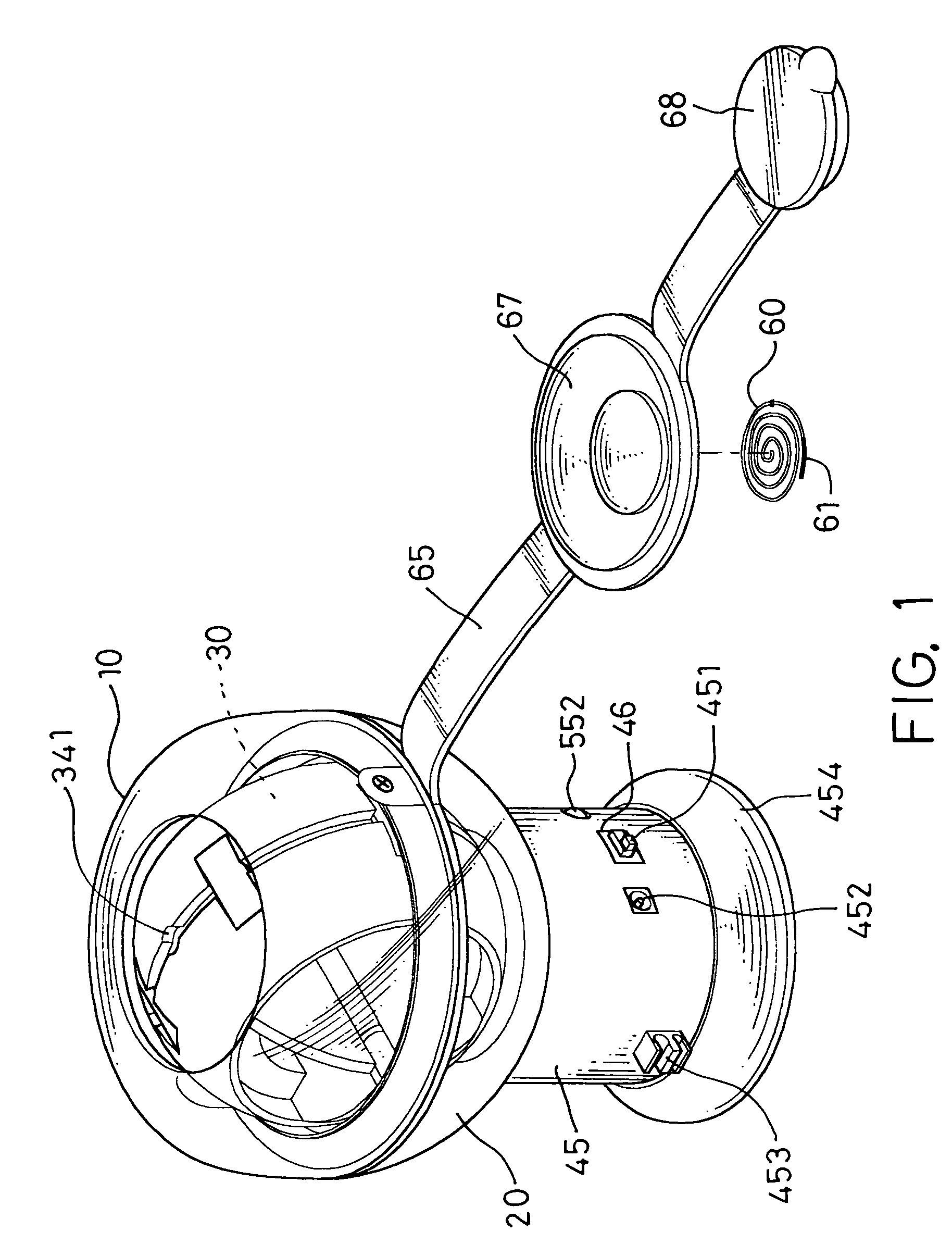
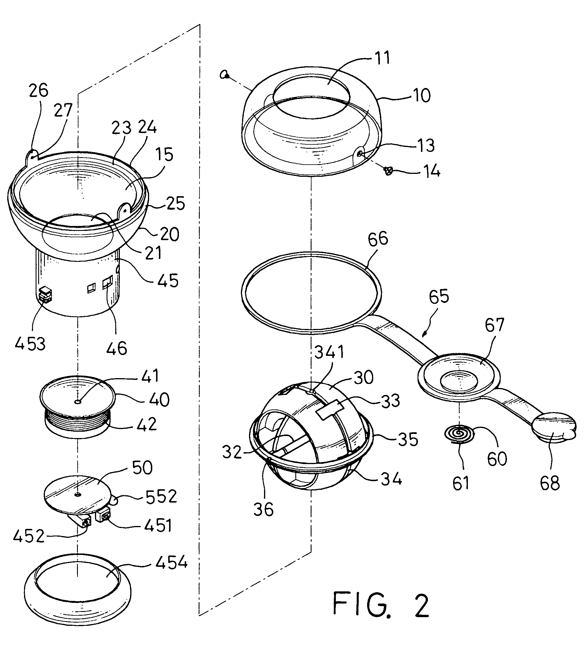
[0013]Please refer to FIGS. 1 to 3 for the perspective view, exploded view, and sectional view of the manual electric generating device 1 in accordance with the present invention respectively. In FIG. 1, the manual electric generating device 1 of the present invention comprises an upper casing 10 of a main body; a lower casing 20 of the main body, a rotor 30, fixed stand 35, a coil 40, a hollow cylinder 45, and a printed circuit 50.

[0014]In FIG. 2, the upper casing 10 of the main body according to the present invention is hemispherical in shape, having a hollow cavity 11 disposed at the top of the upper casing 10 of the main body. The lower casing 20 of the main body is also hemispherical in shape, defining an accommodating space 15 together with the upper casing 11 of the main body for accommodating the rotor 30 and having a hollow cavity 21 disposed at the bottom of the lower casing 20 of the main body and a hollow cylinder 45 for being disposed into the hollow cavity 21, wherein ...


PUM


Abstract

The present invention discloses a manual electric generating device, which comprises an upper casing, a lower casing; a rotor, a fixed stand, a hollow cylinder, a coil for generating power supply; and a printed circuit board for processing and outputting the power supply. The power supply is outputted to a portable electronic device for charging its battery or lighting up its indicating lamp.

Description

FIELD OF THE INVENTION[0001]The present invention relates to a manual electric generating device, more particularly to a manual electric generating device having a wrist exercising effect, in addition to the effect of supplying power to charge an electronic device or use its indicating lamp.BACKGROUND OF THE INVENTION[0002]Please first refer to FIG. 6 for the diagram of the Taiwanese Utility Model Application No. 86212568 entitled “Improved twist trainer”. In FIG. 6, an improved twist trainer 70 comprises a spherical hollow shell 73 comprised of a base 71 and an upper casing 72, a counter 80, a horizontal ring 74 disposed inside the hollow shell 73, and a rotor 75; characterized in that the counter 80 is disposed at the bottom of the base 71, and the horizontal ring 74 is disposed and rotated freely inside the spherical hollow shell 73, and the rotor 75 pivotally coupled to the horizontal ring 74 by a horizontal axle, and a circular groove 76 disposed on the rotor 75 and having a pl...

Claims


Application Information

Patent Timeline
Patent Type & Authority Patents(United States)
IPC IPC(8): H02K7/14A63B23/14H02J7/32H02K7/18
CPCH02K7/1853A63B2021/222Y10T74/12H02J7/32A63B21/222
Inventor SHEN, KUN-TSAI
Owner SHEN KUN TSAI
Why Eureka
Try Eureka