
Developing apparatus for image forming apparatus

a technology of developing apparatus and development apparatus, which is applied in the direction of developers, electrographic process apparatus, instruments, etc., can solve the problems of reducing the amount, affecting the quality of the image, and often fluctuating the amount, and achieves excellent graininess of halftone images, sufficient density, and stable maintenance of the amount of the developer

Inactive Publication Date: 2006-09-05
RICOH KK
View PDF63 Cites 18 Cited by
  • Summary
  • Abstract
  • Description
  • Claims
  • Application Information

AI Technical Summary

Benefits of technology

[0006]An object of the present invention is to provide a developing apparatus capable of retaining a sufficient density by stably maintaining the amount of the developer to be drawn into the development region, and of stably obtaining a high-quality image which has no occurrence of toner scattering or no contamination of the surface but has an excellent graininess of a halftone image, even when copying is repeated for long periods, as well as to provide a process cartridge comprising such a developing apparatus.

Problems solved by technology

However, the amount often fluctuates over time due to change of the developer, which is caused because the developer constantly undergoes a stress generated from the doctor blade by repeated copying.
Especially the drawn amount is reduced over time, which causes on an image a problem, such as an insufficient image density or traces of the carrier ear, and consequently the apparatus wears out.
In Japanese Patent Application Laid-Open No. 2000-47489, for example, the magnetic force distribution of a magnetic roller which acts as magnetic field generating means and is in the developing sleeve is optimized in order to stabilize, for long periods, the amount of the developer to be drawn; however, it is not taken into consideration that the condition of the developer changes because of repeated coping, thus it is understood that the effect of the optimization is not enough to stabilize the amount of the developer to be drawn.

Method used


Image

  • Developing apparatus for image forming apparatus
  • Developing apparatus for image forming apparatus
  • Developing apparatus for image forming apparatus

Examples


Embodiment Construction

)

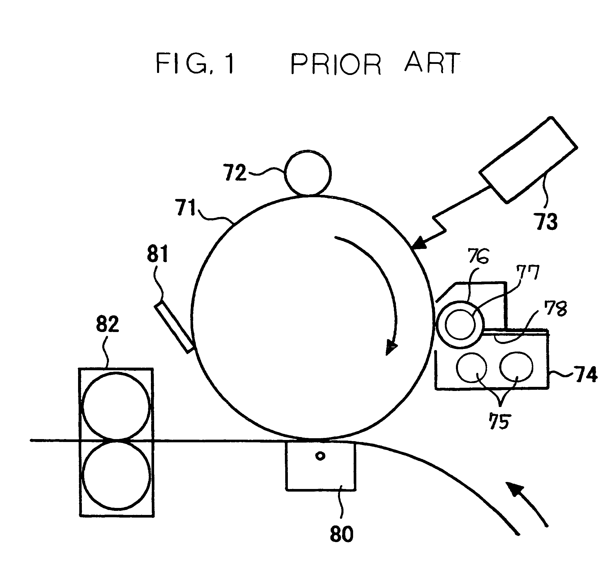
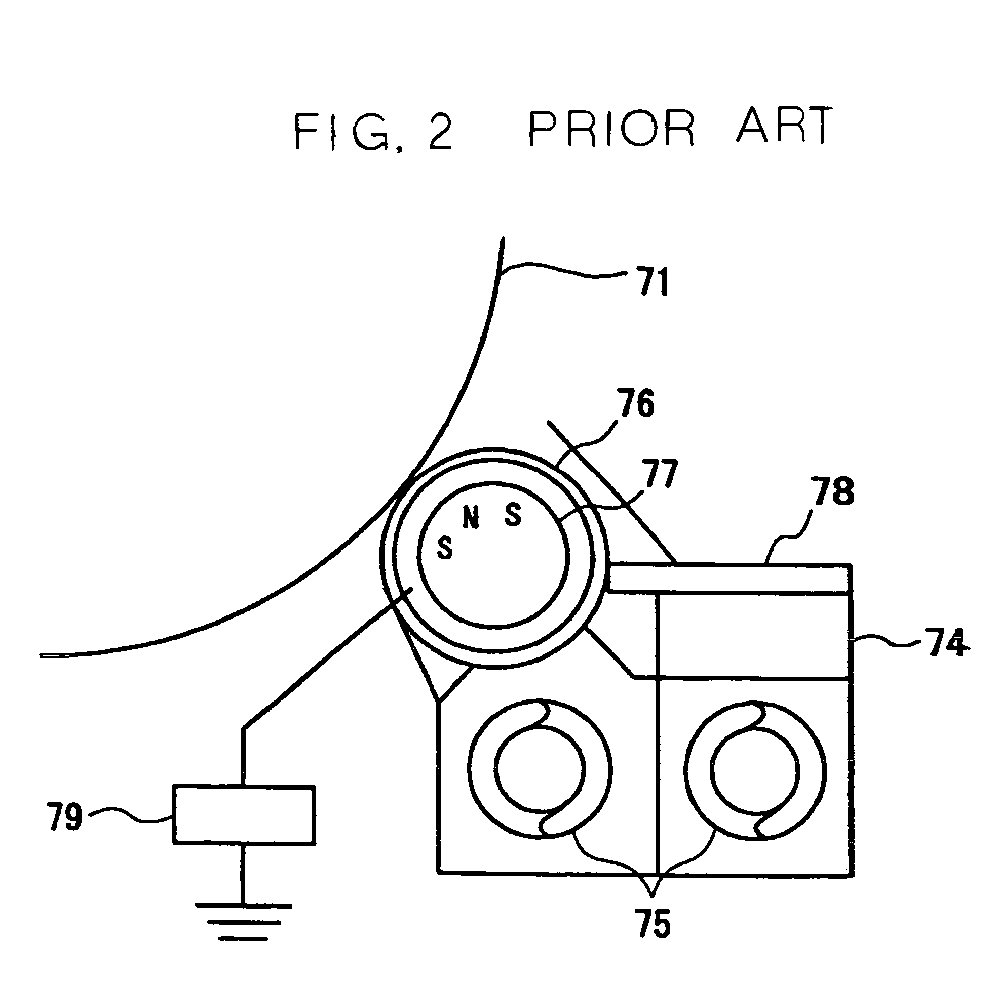
[0036]First of all, a conventional common electrophotographic process where a two-component developer is used is explained using FIGS. 1 and 2.

[0037]In FIGS. 1 and 2, an image support body, which is denoted by a number 71, is formed by applying the photosensitive body as a compress on the circumferential face of the body thereof, and is rotated by a drive mechanism which is not shown, in the direction of an arrow in the figure. This rotating photosensitive body 71 is first charged evenly to a desired electric potential by a charge device 72, and is then exposed to light by a photolithography machine 73, thereby forming an electrostatic latent image corresponding to an image. The electrostatic latent image formed on the photosensitive body 71 is made visible using a developing apparatus 74.

[0038]A developer consisting of a toner and carrier, which is used for development is stored in a developer storage of the developing apparatus 74, and rotatable screws 75 are disposed in the deve...


PUM


Abstract

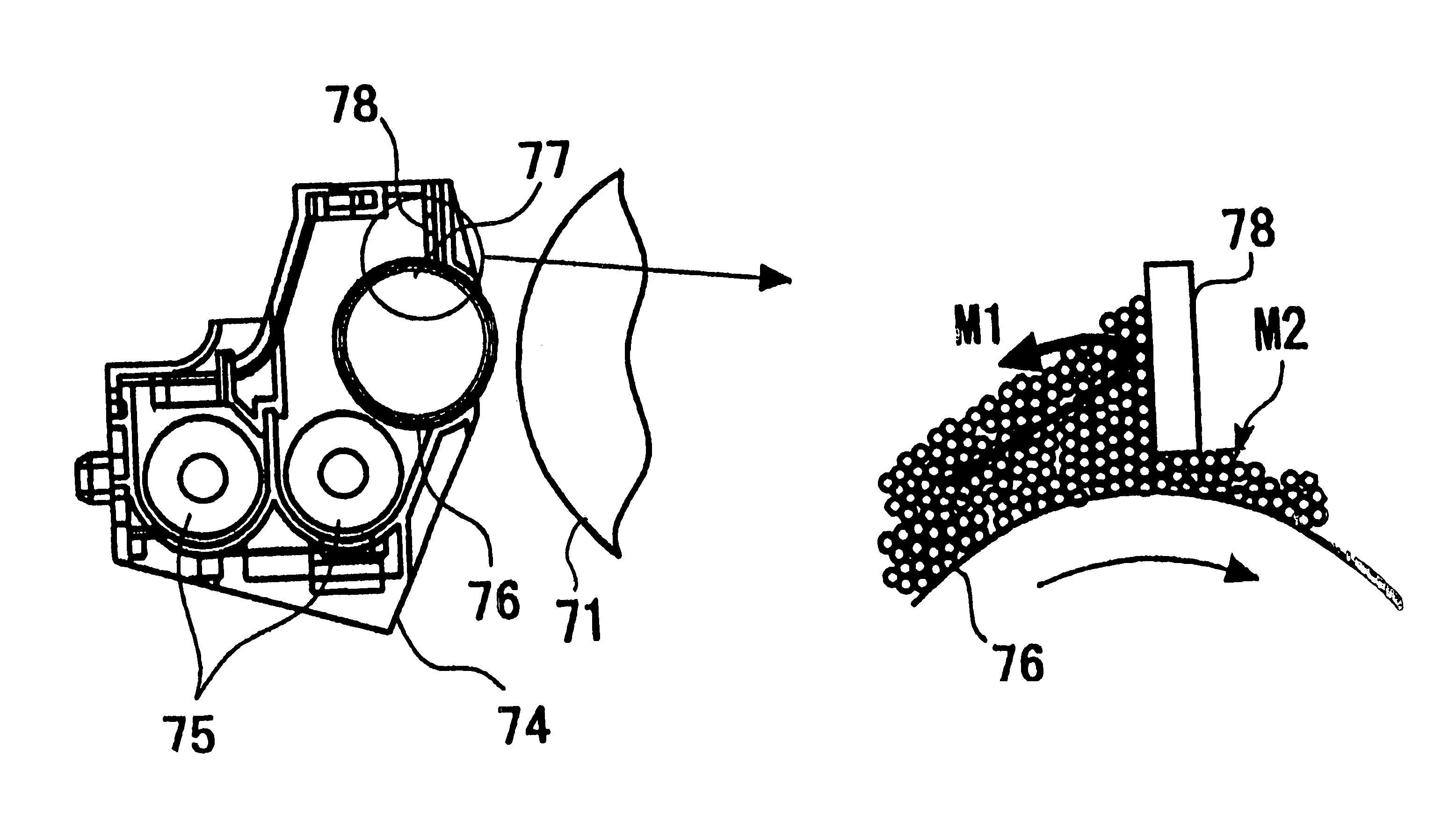
A developing apparatus which uses a two-component developer consisting of a toner and carrier. The ratio between the amount of the developer M1 which is drawn onto a developing sleeve and refluxes while being regulated by a doctor blade, and the amount of the developer (drawn amount) M2 which passes through the doctor blade is M1 / M2<10. The toner is a negatively-charged toner. In a charge amount distribution the number of toners of −1 fc / 10 μm or more is 20% or less of the total number of toners.

Description

BACKGROUND OF THE INVENTION[0001]1. Field of the Invention[0002]The present invention relates to a developing apparatus for a copier, facsimile apparatus, printer, or other similar image forming apparatus that uses an electrophotographic process, and also to a process cartridge comprising this developing apparatus.[0003]2. Description of the Background Art[0004]In the image forming apparatus, such as a copier, printer, or facsimile apparatus, which uses the electrophotographic process, it is important particularly to supply a developer to a development region between a photosensitive body and a developing sleeve in order to stably obtain, for long periods, a high-quality image with a good graininess of a halftone image, with the satisfied image density, and with no defects such as contamination of the surface. The amount of the developer supplied, i.e., the amount of the developer to be drawn, to the development region is set by a magnetic force of a magnetic roller inside the devel...

Claims


Application Information

Patent Timeline
Patent Type & Authority Patents(United States)
IPC IPC(8): G03G15/09G03G9/08G03G9/087G03G15/08
CPCG03G15/0812G03G2215/0609
Inventor KOIKE, TAKAYUKITAKEUCHI, NOBUTAKAIWATA, NOBUOMURAMATSU, SATOSHIMATSUMOTO, JUNICHI
Owner RICOH KK
Learn More