Portable electric cutting device with blower mechanism

a technology of electric cutting machine and blower mechanism, which is applied in the direction of portable power-driven tools, metal sawing accessories, manufacturing tools, etc., can solve the problems of reducing cutting efficiency, affecting cutting accuracy, and affecting cutting accuracy, so as to prevent blurring or erasing of marking lines and reliably confirm positional relationships.

Inactive Publication Date: 2006-09-12
KOKI HLDG CO LTD
View PDF23 Cites 38 Cited by
  • Summary
  • Abstract
  • Description
  • Claims
  • Application Information

AI Technical Summary

Benefits of technology

[0014]In the view of foregoing, it is an object of the present invention to overcome the above problems, and also to provide a portable electric circular saw that prevents the marking line from being blurred or erased during cutting operation, enabling a user to reliably confirm the positional relationship between a blade edge of a saw blade and a marking line on a cutting object during the operations.
[0015]Another object of the present invention is to provide a portable electric circular was that can effectively prevent accumulation of dust on an cutting object by using fanned air generated for cooling a motor so as to improve cutting accuracy and cutting efficiency.
[0016]Still another object of the present invention is to provide a portable electric circular saw that can selectively prevent dust from being dispersed by the fanned air, without increasing the number of components.
[0017]Still another object of the present invention is to provide a portable electric circular saw that can suppress the generation of noise without reducing the cooling performance of the fan.

Problems solved by technology

However, when the bottom surface of the base slides on the cutting object, the marked line may be blurred or erased due to friction between the bottom surface of the base and the upper surface of the cutting objects, disabling the user to confirm the positional relationship between the blade edge and the marking line.
Also, if ink of the marking line transfers onto the bottom surface when sliding, then the ink may get back to the cutting object so that the cutting object gets dirty.
Further, if a large volume of saw dust produced during the cutting operation piles on the cutting object, the marking line becomes invisible.
In this case, the user can no longer confirm the positional relationship between the blade edge of the saw blade and the marking line, resulting in degradation of cutting accuracy and decreasing in cutting efficiency.
However, dust can be produced during, not only cutting operations, but also other operations using various other tools.
In this case, even if such a dust collector is used during cutting operations, dust may accumulate on the cutting object to hide the marking line.
This reduces the efficiency of the cutting operation.
This reduces both the cutting accuracy and the efficiency of the cutting operation.
This arises a problem of generation of noise in radially remote areas.
However, this results in reducing the flow rate of the fanned air, thereby degrading the cooling performance of the fan.
However, the guide pipe becomes an obstacle when confirming the positional relationship between the marking line and the blade edge of the saw blade, reducing the visibility of the marking line.
Additionally, the assembling efficiency falls and the cost rises because of the increased number of the components.

Method used


Image

  • Portable electric cutting device with blower mechanism
  • Portable electric cutting device with blower mechanism
  • Portable electric cutting device with blower mechanism

Examples


first embodiment

[0075]Next, portable electric circular saws according to embodiments of the present invention will be described with reference to the accompanying drawings. First, a portable electric circular saw according to the present invention will be described with reference to FIGS. 1–28.

(1) Basic Configuration

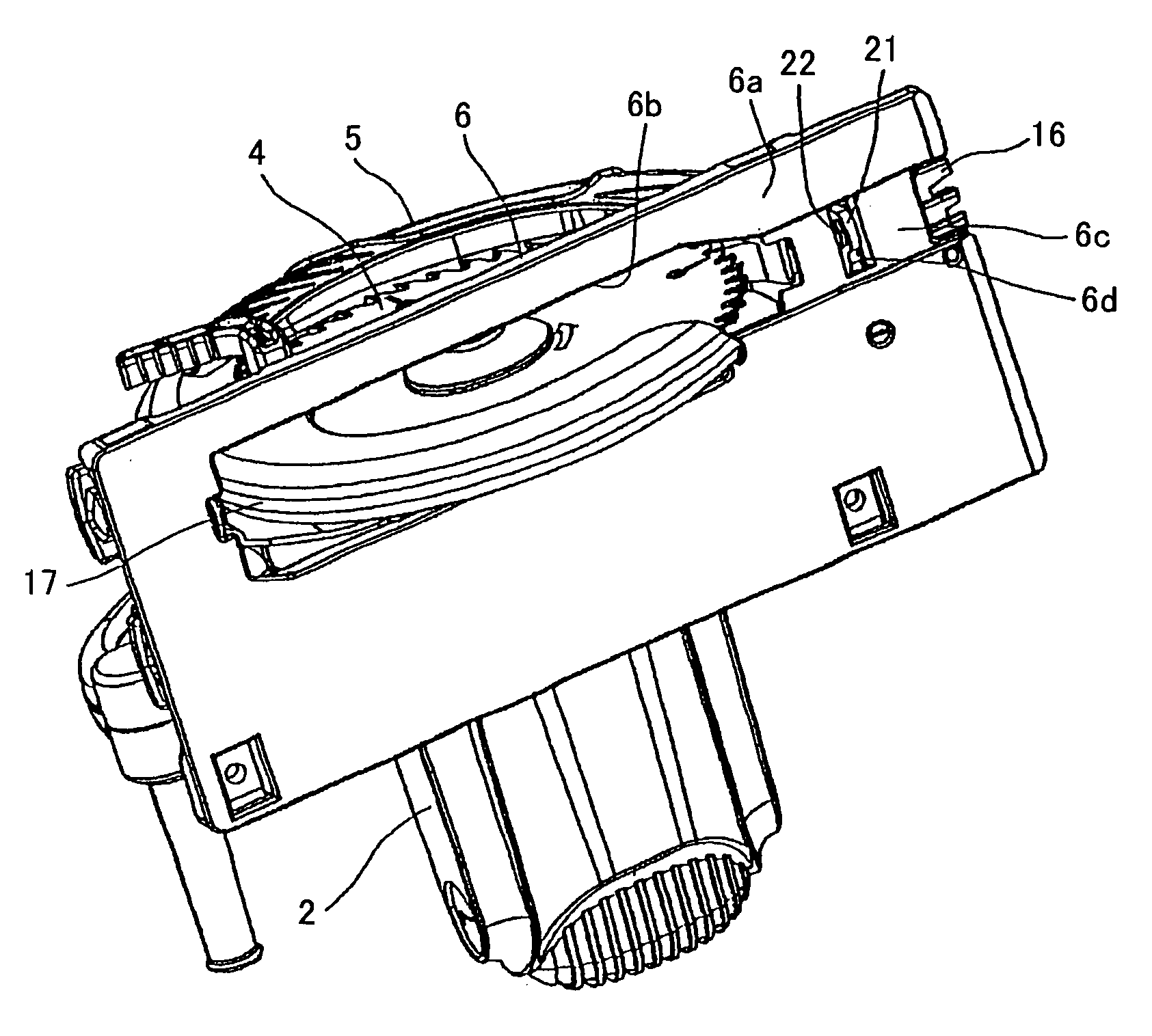
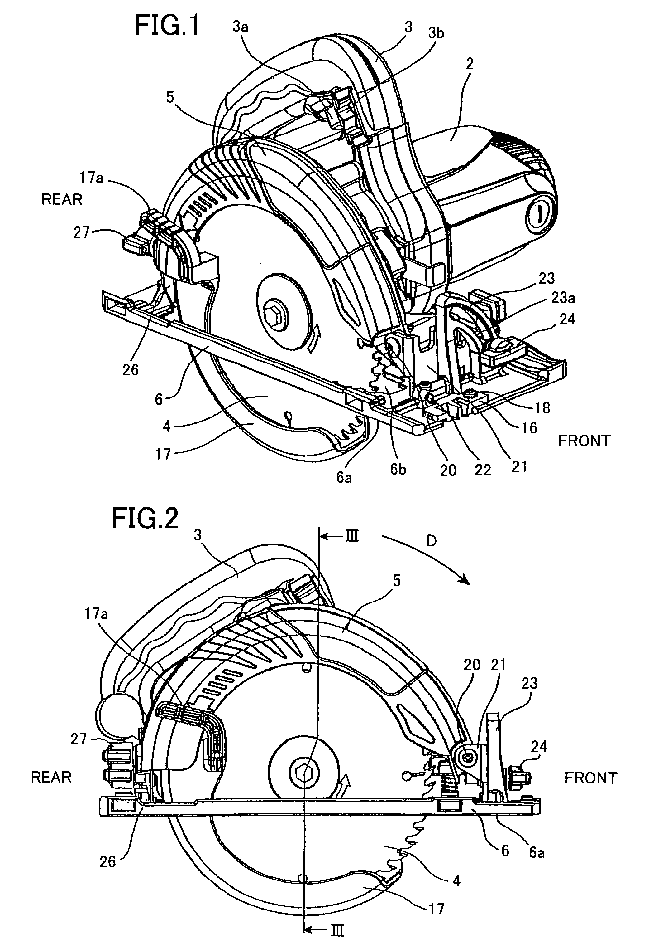
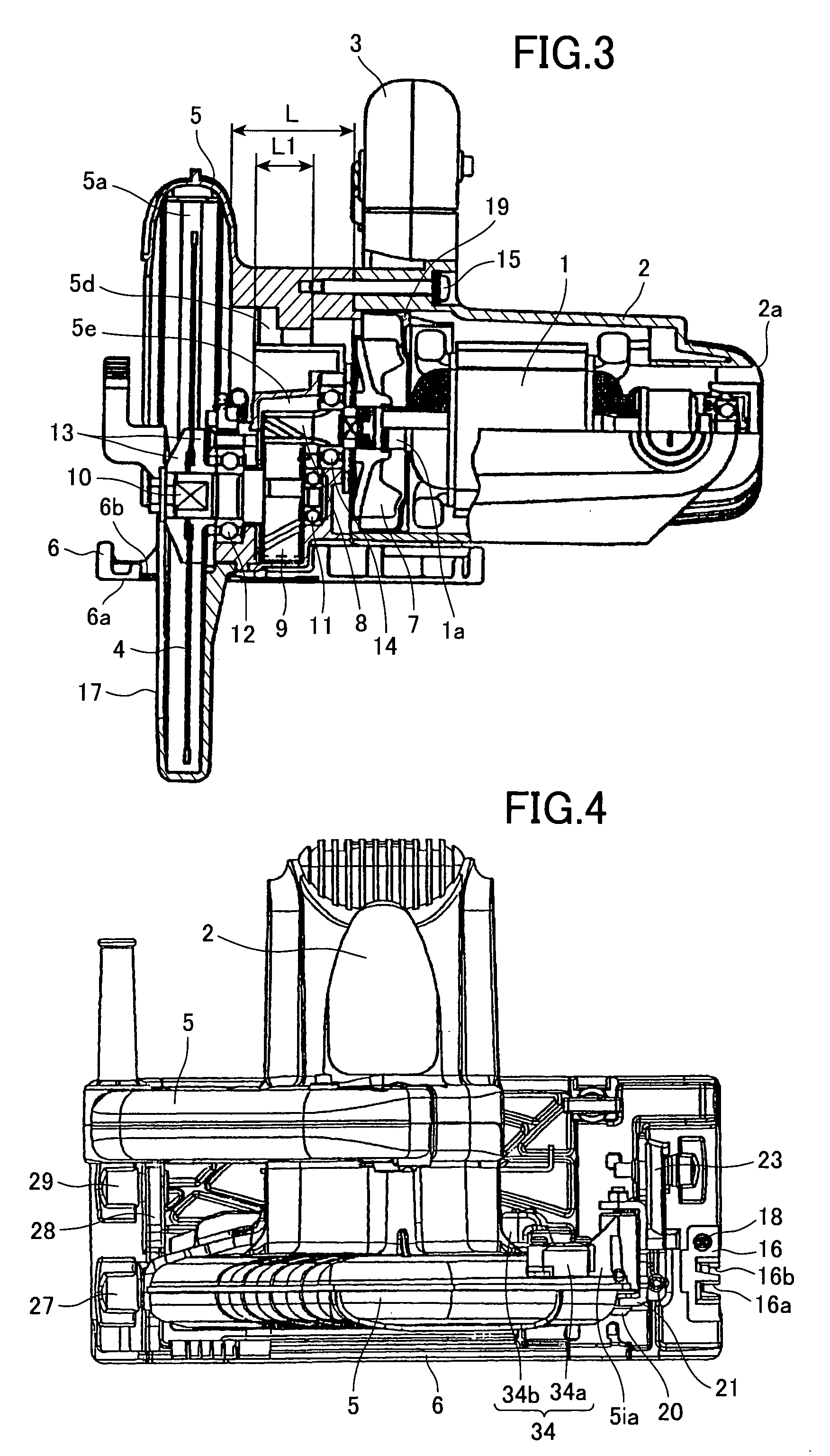
[0076]As shown in FIGS. 1–3, the portable electric circular saw of the present embodiment includes a motor 1, a housing 2, a handle 3, a saw blade 4, a saw cover 5, a base 6, and a fan 7. The motor 1 drives the saw blade 4 to rotate. The housing supports and houses the motor 1. The handle 3 is formed integral with the housing 2 or linked to the housing 2 as a separate member. A user can turn ON and OFF the motor 1 through operation on a switch 3a of the handle 3. The saw cover 5 is attached to the housing 2 and has a saw blade housing section 5a. The saw blade 4 has a fan-side lateral surface facing the fan 7 and a housing-section-side lateral surface facing the saw blade housing sectio...

third embodiment

[0142]Here, the portable electric miter of the third embodiment could be modified so that the other side edge of the groove 206c tilts outward toward the saw blade 4, that is, the edge tilts to the direction opposite to the housing 2 toward the saw blade 4. It is also possible to form the groove 206c such that the depth of the groove 206c increases toward the opening 206b. In this case, the upper wall of the groove 206c locates above the bottom surface 206a of the base 206 at the position close to the opening 206b. In these manner also, it is possible to increase the amount of fanned air introduced into the groove 206c.

[0143]Next, portable electric circular saws according to fourth through sixth embodiments of the present invention will be described in this order. The portable electric circular saws of the fourth through sixth embodiments are any of the first through third embodiments provided with an air-blow regulating mechanism to be described later that regulates the amount of ...

fourth embodiment

[0144]First, the portable electric circular saw will be described in detail with reference to FIGS. 36 and 37. The air-blow regulating mechanism includes a groove 306f formed in a bottom surface 306a of a base 306, a shield member 351 formed with a long through hole 351a and housed in the groove 306f, and a screw 352 engaged with the base 306 through the hole 351a. The groove 306f is formed at the rear of a hole 306d with respect to the cutting direction. The groove 306f is in fluid communication with the groove 306c and has substantially the same depth as the groove 306c. The shield member 351 is slidable along the groove 306f between a non-shielding position shown in FIG. 36 and a shielding position shown in FIG. 37. The screw 352 locks and unlocks the sliding position of the shield member 351 relative to the base 306. That is, the shield member 351 is slidable within the length of the hole 351a, and its position is fixed by tightening the screw 352.

[0145]When the shield member 3...


PUM

PropertyMeasurementUnit
angleaaaaaaaaaa
areaaaaaaaaaaa
thicknessaaaaaaaaaa

Abstract

Fanned air generated by a fan to cool a motor is discharged from a housing through fanned air discharge ports toward an opening formed in a base. The fanned air discharged toward the opening is then introduced into a groove in fluid communication with the opening. The groove is formed in a bottom surface of the base and has an open side at a front side of the base. The fanned air is then discharged from the front side of the base, blowing off saw dust on a cutting object so as to prevent dust from accumulating on a marking line on the cutting object.

Description

BACKGROUND OF THE INVENTION[0001]1. Field of the Invention[0002]The present invention relates to a portable electric cutting machine, and more particularly to a portable electric cutting machine provided with an air-discharge mechanism for discharging air from a housing into a saw blade housing section of a saw cover.[0003]2. Related Art[0004]When cutting a cutting object, such as timber, by using a portable electric cutting machine (hereinafter referred to as “portable electric circular saw”), a marking line is drawn on the cutting object and then the object is cut along the marking line for the purpose of improving the cutting accuracy. More specifically, a guide piece for indicating the edge position of the saw blade is disposed at the front end of a base so that the guide piece locates on an imaginary line extended in a cutting direction from the saw blade. A user can cut the cutting object while directly confirming the positional relationship between the blade edge of the saw b...

Claims


Application Information

Patent Timeline
Patent Type & Authority Patents(United States)
IPC IPC(8): B23D47/02B23D59/00B23Q11/00B27B9/00
CPCB23D59/006B27B9/00B23Q11/005
Inventor YOSHIDA, KENICHIROUTANIMOTO, HIDEYUKINISHIKAWA, TOMOMASATAKANO, SHINJINONAKA, TAKUMANIWA, KENJIIMAI, TERUOSHIMADA, SATOSHI
Owner KOKI HLDG CO LTD
Why Eureka
Try Eureka