Mole trap

a technology of mole traps and traps, applied in the field of mole traps, can solve the problems of destroying the mole, destroying the jaws and affecting the habitation of the mole,

Active Publication Date: 2006-09-12
HOLTGREFE SR THOMAS H
View PDF27 Cites 5 Cited by
  • Summary
  • Abstract
  • Description
  • Claims
  • Application Information

AI Technical Summary

Problems solved by technology

When a mole travels between the jaws, vibration or other disturbance caused by the mole's movement may release the trigger so that the jaws close and destroy the mole.
Conventional spring-loaded traps may be unstable when placed in the ground.
Sometimes, the ground elevation at a mole burrow may be rough and uneven.

Method used


Image

  • Mole trap
  • Mole trap
  • Mole trap

Examples


Embodiment Construction

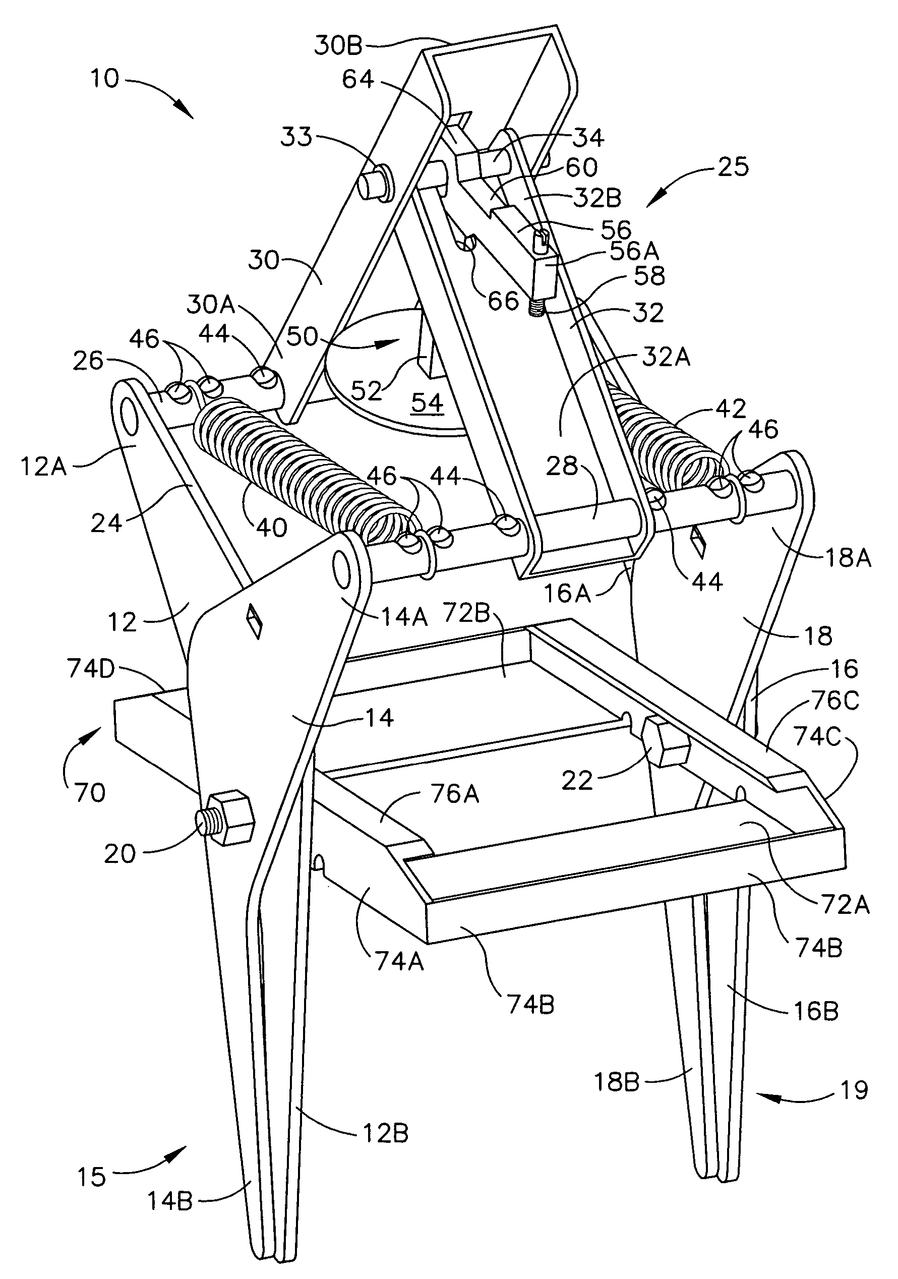
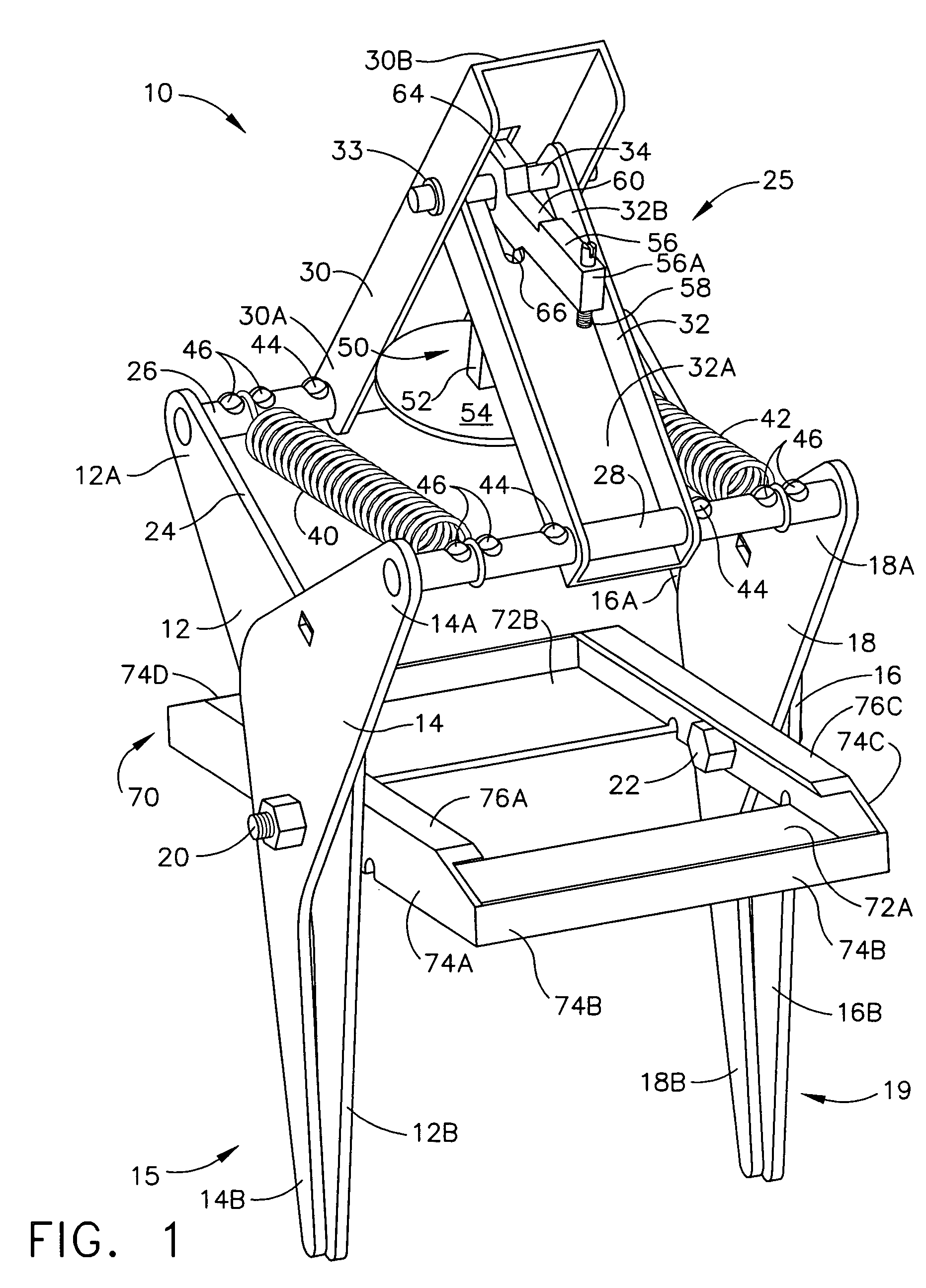
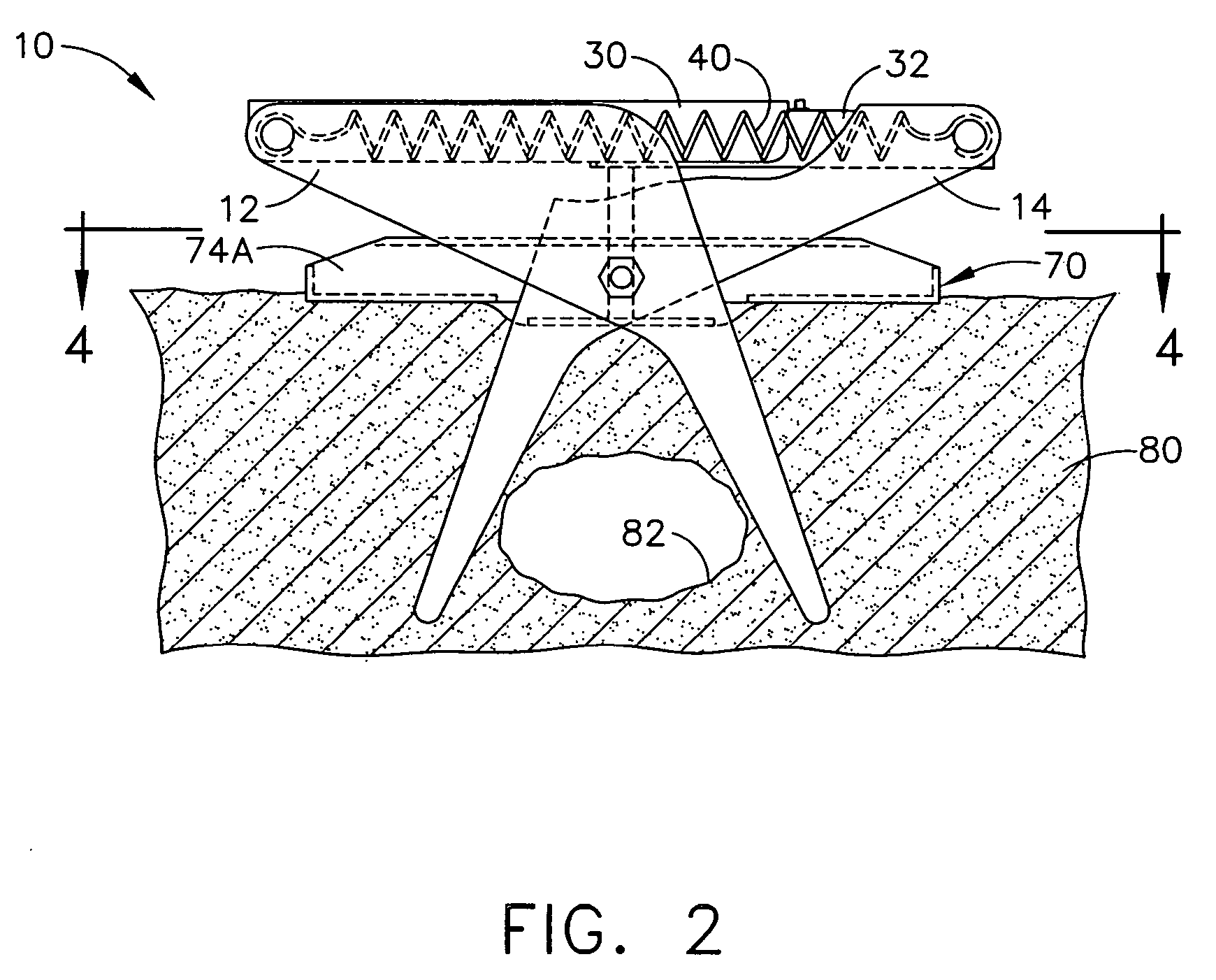
[0015]A merely illustrative embodiment of the mole trap of the present example, indicated generally at 10, is illustrated in FIGS. 1–3. Mole trap 10 includes first angled member 12 and second angled member 14. Angled member 12 terminates in support end 12A and opposite blade end 12B. By being “angled,” angled member 12 has an offset between support end 12A and support end 12B. In the present example, near the mid-point of angled member 12, angled member 12 is angled or bent to form an angle greater than 90°. However, it will be appreciated that other angular configurations for angled member 12 may be used. It will also be appreciated that angled member 12 need not be angled or bent at all. To the extent that angled member 12 is angled or bent, such angle or bend may be located at any suitable position along angled member 12.

[0016]In a similar manner, angled member 14 includes support end 14A and blade end 14B. Angled members 12 and 14 are hinged together by fastener 20 to form first...


PUM


Abstract

A mole trap has a pair of spring-loaded jaws. A platform is pivotally connected to the jaws to limit the travel of the trap into the ground and to stabilize the trap on the ground when it is set. A lever assembly forces the jaws open and sets the trap. An adjustable trigger mechanism is positioned on the ground above a mole burrow. The disturbance of a mole traveling beneath the trigger causes the lever assembly to collapse, thereby permitting the jaws to close and destroy the animal.

Description

BACKGROUND OF THE INVENTION[0001]The present invention relates to an animal trap that is particularly well-suited for destroying or otherwise trapping moles in their burrows.[0002]Mole traps may include spring-loaded jaws and a trigger. Such traps may be set so that the jaws are positioned on either side of a mole burrow or tunnel. A trigger may be positioned on the ground above the burrow. When a mole travels between the jaws, vibration or other disturbance caused by the mole's movement may release the trigger so that the jaws close and destroy the mole. Various examples of traps may be found in U.S. Pat. Nos. 472,038; 1,296,407; 1,923,039; 2,525,383; and 4,765,087. U.S. Pat. No. 4,765,087 is incorporated by reference herein.[0003]Conventional spring-loaded traps may be unstable when placed in the ground. Particularly after a rain shower, a trap may settle and shift so that a jaw is exposed in the mole burrow, possibly minimizing the chance that a mole will pass between the jaws. A...

Claims


Application Information

Patent Timeline
Patent Type & Authority Patents(United States)
IPC IPC(8): A01M23/26
CPCA01M27/00A01M23/265
Inventor HOLTGREFE, SR., THOMAS H.
Owner HOLTGREFE SR THOMAS H
Why Eureka
Try Eureka