Bending device for tube

a technology of bending device and long tube, which is applied in the field of efficient bending device for long tube, can solve the problems of increasing the number of processes, the inability to perform bending in the whole process, and the inability to shorten the bending time, so as to improve the precision and efficiency, and the process is processed. to be, the effect of improving efficiency

Inactive Publication Date: 2006-09-12
USUI KOKUSAI SANGYO KAISHA LTD
View PDF13 Cites 22 Cited by
  • Summary
  • Abstract
  • Description
  • Claims
  • Application Information

AI Technical Summary

Benefits of technology

[0007]Furthermore, the conventional device requires a twisting time when a tube twisting angle is large (when it is from 90 degrees to 180 degrees) after bending a tube until a subsequent bending plane is secured. Especially in the case that the number of the bending processes is large and a tube, which has undergone bending already, is long, a high tube twisting speed causes change in shape, and thereby, an error in bending shape, so that the tube should be twisted at a low speed. This causes a disadvantage that it takes long time for twisting the pipe. The present invention is to overcome the above disadvantages in the conventional device and is to provide a tube bending device including a pair of bending units having one or both of draw bending (draw bend) and compression bending (compression bend) functions, the tube bending device capable of bending in all processes in a unit of device by providing the bending unit with a vertical plane rotating mechanism.
[0008]The tube bending device in accordance with the present invention is a bending device for a tube comprising: at least one bending die; a clamp jig for carrying out bending by rotation at a predetermined angle on a circumferential surface of the bending die through a tube to be processed with the tube pressured against the circumferential surface; and a reaction force receiving roller, the bending device for a tube further comprising: a movable type of tube bending unit capable of moving in a longitudinal direction of the tube to be processed or a fixed type of tube bending unit; and a tube twisting unit, which rotates freely at a predetermined angle with a center of the tube to be processed being a core of an axis, and which can move the tube to be processed to a location corresponding to a bending shape, wherein the reaction force receiving roller of the tube bending unit is made rotatable concentrically with the bending die and the clamp jig so that at least one of functions of draw bending and compression bending for the tube to be processed would be achieved, and wherein the tube bending unit is provided rotatably in a vertical plane about an axis parallel to a core of an axis of the tube to be processed, and thereby, the amount of displacement in an operation of twisting a tube to be processed can be reduced.
[0010]In the present invention, providing the unit for compression bending so as to be rotatable concentrically with the unit for draw bending allows a tube to be processed to be bent in the opposite direction by means of the unit for compression bending, providing the tube bending unit rotatably in a vertical plane about an axis parallel to a core of an axis of the tube to be processed allows the amount of displacement of the tube to be processed in an operation of twisting the tube to be processed to be reduced. Accordingly, no interference between the tube to be processed and the bending device or the floor surface occurs regardless of a tube bending or twisting angle, so that bending in the whole processes can be carried out in a unit of device. This allows a great effect to be obtained that the bending can be performed more efficiently in addition to further improvement in preciseness and efficiency in bending a tube having different radius and a long tube. Moreover, simultaneously rotating the tube bending unit and the twisting unit in an adverse direction allows a bending plane to be secured in a half time of the time for the case that a single unit rotates in one direction. This causes great effects that the bending time can be shortened and that a part to which bending has been completed is not changed in shape since the tube is not twisted at a large twisting angle, and thereby, bending can be precisely carried out without any error in bending shape.

Problems solved by technology

In the conventional tube bending device, however, a tube bending unit, which comprises at least one bending die, a clamp jig for carrying out bending by rotation at a predetermined angle on a circumferential surface of the bending die through a tube to be processed with the tube pressured against the circumferential surface and a reaction force receiving roller, is limited in bending radius due to exclusive use of the bending die for the respective bending directions and is limited only to draw bending (draw bend) since the reaction force receiving roller has no bending function due to no rotation with respect to the clamp jig, which rotates at a predetermined angle along a circumferential surface of the bending die to carry out bending.
Therefore, in the case of the conventional device, a certain tube bending or twisting angle causes large displacement in a twisting operation, and thereby, interference with a unit on the reaction force receiving roller side or such occurs, so that bending in the whole processes cannot be performed by means of a unit of the device in some cases.
This necessitates increase in the number of processes and causes a disadvantage that the bending time cannot be shortened.
Furthermore, the conventional device requires a twisting time when a tube twisting angle is large (when it is from 90 degrees to 180 degrees) after bending a tube until a subsequent bending plane is secured.
Especially in the case that the number of the bending processes is large and a tube, which has undergone bending already, is long, a high tube twisting speed causes change in shape, and thereby, an error in bending shape, so that the tube should be twisted at a low speed.
This causes a disadvantage that it takes long time for twisting the pipe.

Method used


Image

  • Bending device for tube
  • Bending device for tube
  • Bending device for tube

Examples


Embodiment Construction

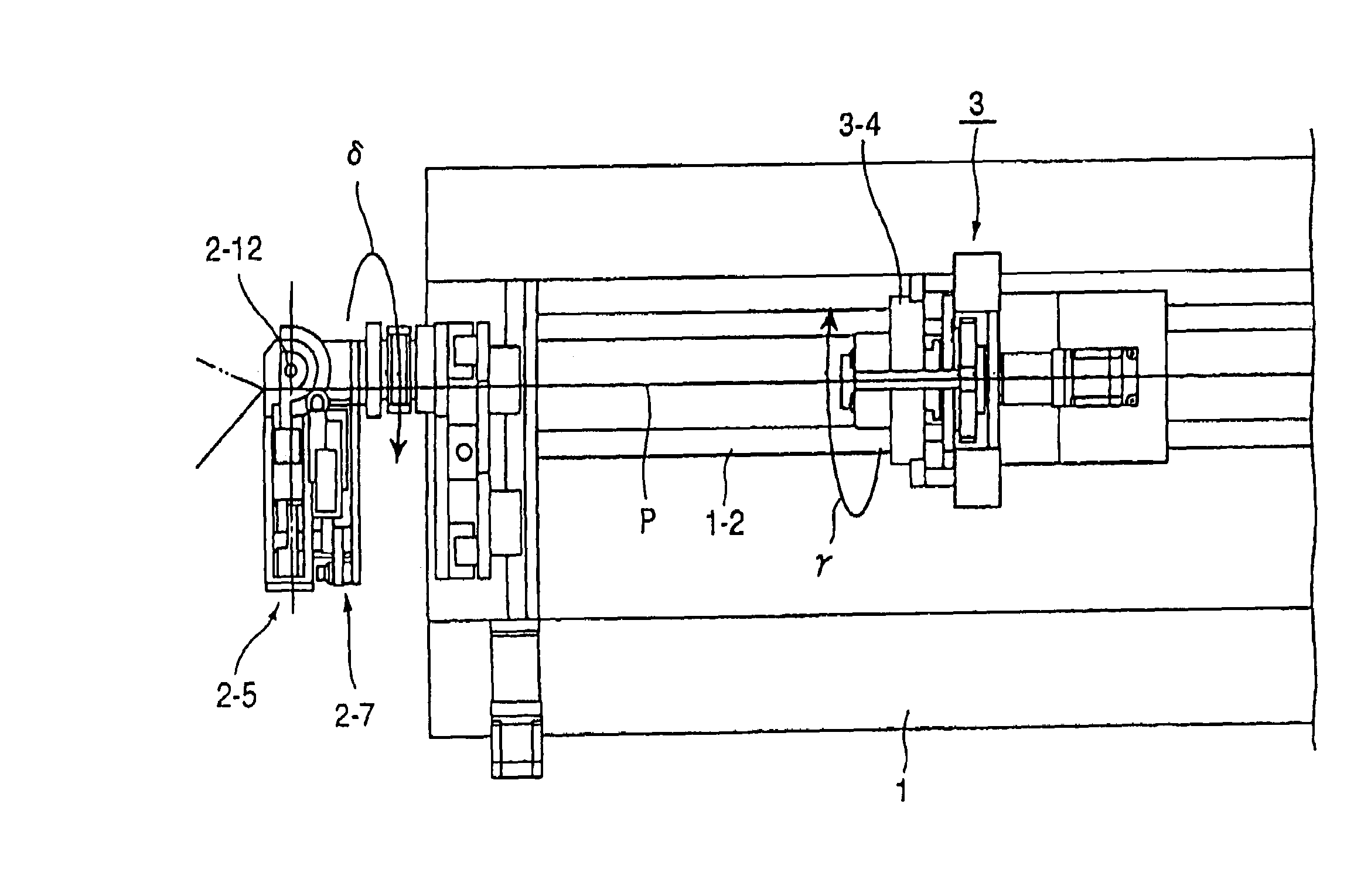
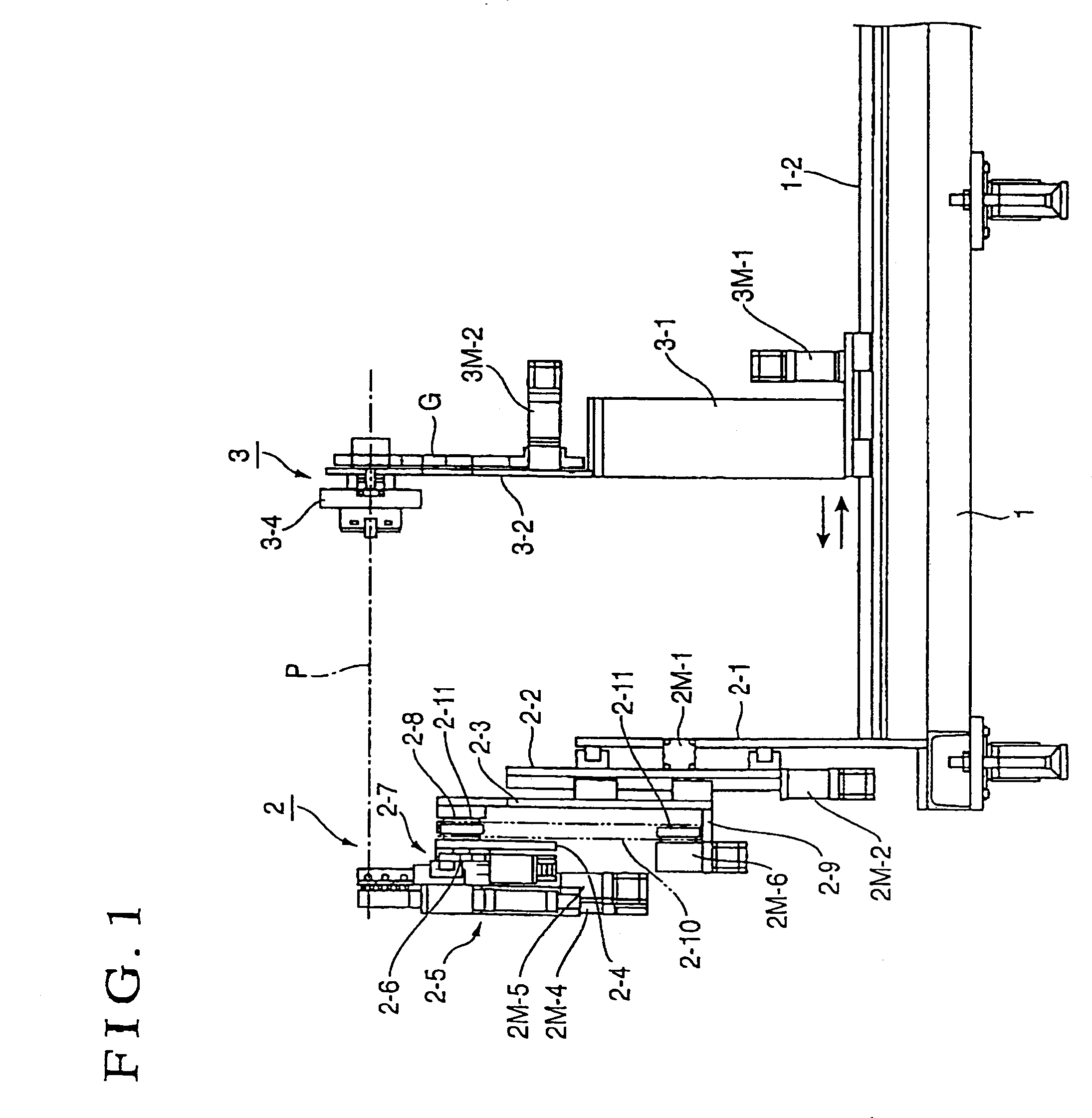
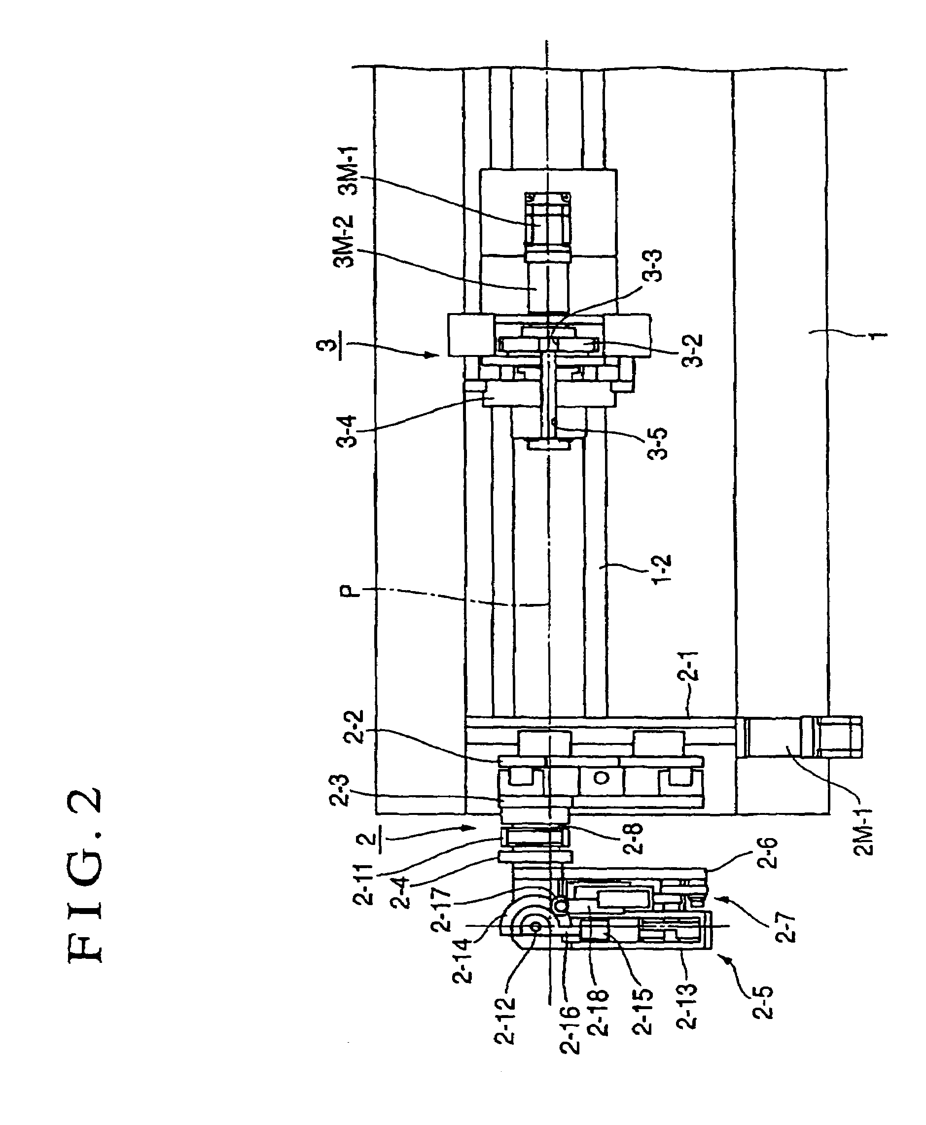
[0018]In the present invention, 1 denotes a pedestal, 2 denotes a tube bending unit, 3 denotes a tube twisting unit and P denotes a tube to be processed. A bending device in which a couple of bending units has both functions of draw bending (draw bend) and compression bending (compression bend) will be described as an example here.

[0019]That is to say, the tube bending device in accordance with the present invention comprises the tube bending unit 2 and the tube twisting unit 3, which are mounted on the pedestal 1, in the both cases of a tube bending device exemplary shown in FIGS. 1 to 6 and a tube bending device shown in FIG. 7 In the tube bending device exemplary shown in FIGS. 1 to 6, the tube bending unit 2 is fixedly mounted on the pedestal 1 while the tube twisting unit 3 is placed on the pedestal 1 so as to be movable in a direction of a core of an axis of the tube P to be processed. On the other hand, in the tube bending device shown in FIG. 7, mounted on the pedestal 1 are...


PUM

PropertyMeasurementUnit
twisting angleaaaaaaaaaa
angleaaaaaaaaaa
reaction forceaaaaaaaaaa

Abstract

A tube bending device having draw-bending and compression-bending functions and capable of bending in all processes in a unit of device is provided. The device performing bending by rotating the tube at a predetermined angle with the tube pressured against a circumferential surface of a bending die, the device including a movable type of tube bending unit movable in a longitudinal direction of a tube to be processed or a fixed type of tube bending unit and a tube twisting unit for rotating the tube freely at a predetermined angle with a center of the tube being an axis core is characterized in that the tube bending unit has one or both of draw-bending and compression-bending functions and is provided rotatably in a vertical plane about an axis parallel to the axis core of the tube so that the displacement amount in a tube twisting operation can be reduced.

Description

BACKGROUND OF THE INVENTION[0001]1. Technical Field[0002]The present invention relates to an efficient bending device for a long tube made of metal such as a steel tube, a stainless steel tube, a copper tube, a titanium tube and an aluminum tube.[0003]2. Background Art[0004]A double bender having two right and left units of pressure die unit disclosed in JP-B-8-29358, for example, has been conventionally proposed as the above-mentioned type of bending device (bender device). In the right and left double bending type of bender, a bending unit mechanism has a single structure and is arranged to freely move up and down with respect to a horizontal position of a long tube, which is held, and a chuck mechanism portion is interlocked with a feeding mechanism operating in a back and forth direction on a moving pedestal while the moving pedestal is arranged to be capable of parallel movement in the right and left direction.[0005]Further, as another known tube bending device, there has been ...

Claims


Application Information

Patent Timeline
Patent Type & Authority Patents(United States)
IPC IPC(8): B21D7/024B21D7/025B21D7/08
CPCB21D7/024B21D7/08
Inventor SAEGUSA, SHIGERU
Owner USUI KOKUSAI SANGYO KAISHA LTD
Why Eureka
Try Eureka