Active protection device and associated apparatus, system, and method

a protection device and active technology, applied in the field of defensive devices, can solve the problems of piercing of the armor of the platform, affecting the effectiveness of the protective weapon system, and causing damage to the platform, etc., and achieve the effects of wide protection, advantageous and effective, and high concentration of power

Inactive Publication Date: 2006-09-12
CHANG IND INC
View PDF38 Cites 36 Cited by
  • Summary
  • Abstract
  • Description
  • Claims
  • Application Information

AI Technical Summary

Benefits of technology

[0012]To reiterate, embodiments of the present invention provide an interceptor device having certain advantageous features. For example, some embodiments implement a cuing sensor that is capable of, for instance, detecting the threat(s); discriminating the threat(s) from non-threats, such as small to medium caliber bullets and flying debris; determining the type of threat; calculating the threat flight path, including distance, speed, and angular position, to determine if the platform or vehicle to be protected will actually be threatened; timely directing the launch of an appropriate interceptor device to defeat the threat; and then destroying the threat upon impact, causing an asymmetric detonation of the threat, or otherwise disabling the threat. Accordingly, an interceptor device can be timely launched with an appropriate launch time and exit speed so to engage the threat at a pre-determined safe distance (otherwise referred to herein as the intercept zone) from the platform.
[0014]In another example (“Type B”), the CM, when deployed by the detonating device(s), generates a relatively broad band of outgoing particles which are directed radially outward of the interceptor device in order to hit the warhead section of a CE threat. Such a countermeasure may be used, for example, against a threat having a hardened area around the warhead section. The radially outgoing broad band or ring of particles covers a relatively large intercepting area having a minimum diameter of, for example, about 10 feet so as to thereby provide relatively broad protection for the platform against such a threat. The interceptor device will, in some instances, have onboard fusing sensors to determine the appropriate timing for actuating the detonating device(s) and deploying the CM. When deployed, the speed of the CM particles should preferably be as high as possible and, in some instances, preferably exceeding about 5,000 ft / sec.
[0015]In still another example (“Type C”), the CM, when deployed by the detonating device(s), generates a focused thin ring of outgoing CM particles. The resulting particles thus have highly concentrated power for hitting a single or multiple selected areas on the threat. Such a CM configuration is particularly advantageous and effective against a KE threat so as to, for example, cause the threat to break up and / or to be diverted. Such a CM should preferably be associated with, for instance, a fusing sensor or fusing sensor system on the interceptor device for accurately locating and determining the speed of the incoming threat in order for the CM be deployed so as to accurately hit the critical area(s) of the threat. Preferably, the speed of the radially outgoing CM particles must be as high as possible, in some instances exceeding about 10,000 ft / sec. In order to ensure a high or maximized impact power for the CM particles, the CM particles can be concentrated into one sector of the circular ring by using appropriate parameters such as, for example, the configuration and / or actuation procedure of the detonating device(s).

Problems solved by technology

In still other instances, the flight trajectory of the KE threat can be diverted such that the threat is caused to miss the target platform.
However, for CE threats, the warhead of the threat should be hit such that the warhead is asymmetrically detonated and thus becomes unable to form a penetrator or a penetrating jet typically characterizing such a threat, since simply destroying the body of the CE threat could still allow the penetrator formation and result in the piercing of the armor of and subsequent damage to the platform.
However, these protective weapon systems may not be particularly effective against an incoming CE threat since such systems may not be sufficiently accurate to ensure that the warhead section of the CE threat is actually hit and disabled or diverted.
In addition, such protective weapon systems may also be incapable of intercepting and disabling a KE threat.
Furthermore, the effectiveness of these weapon systems against multiple threats, as well as the capability thereof of discriminating against false targets, may be uncertain.

Method used


Image

  • Active protection device and associated apparatus, system, and method
  • Active protection device and associated apparatus, system, and method
  • Active protection device and associated apparatus, system, and method

Examples


Embodiment Construction

[0026]The present invention now will be described more fully hereinafter with reference to the accompanying drawings, in which some, but not all embodiments of the invention are shown. Indeed, this invention may be embodied in many different forms and should not be construed as limited to the embodiments set forth herein; rather, these embodiments are provided so that this disclosure will satisfy applicable legal requirements. Like numbers refer to like elements throughout.

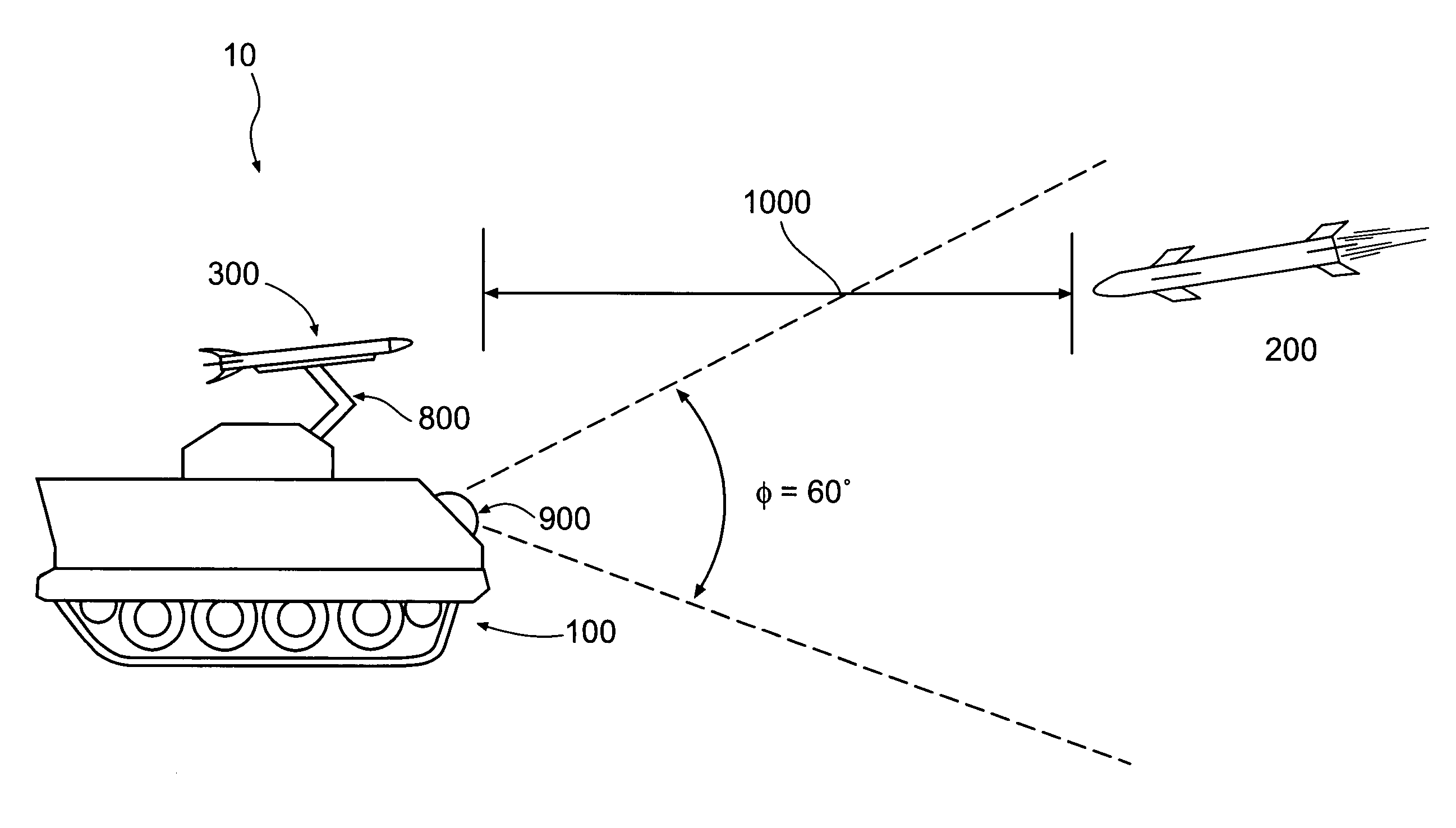
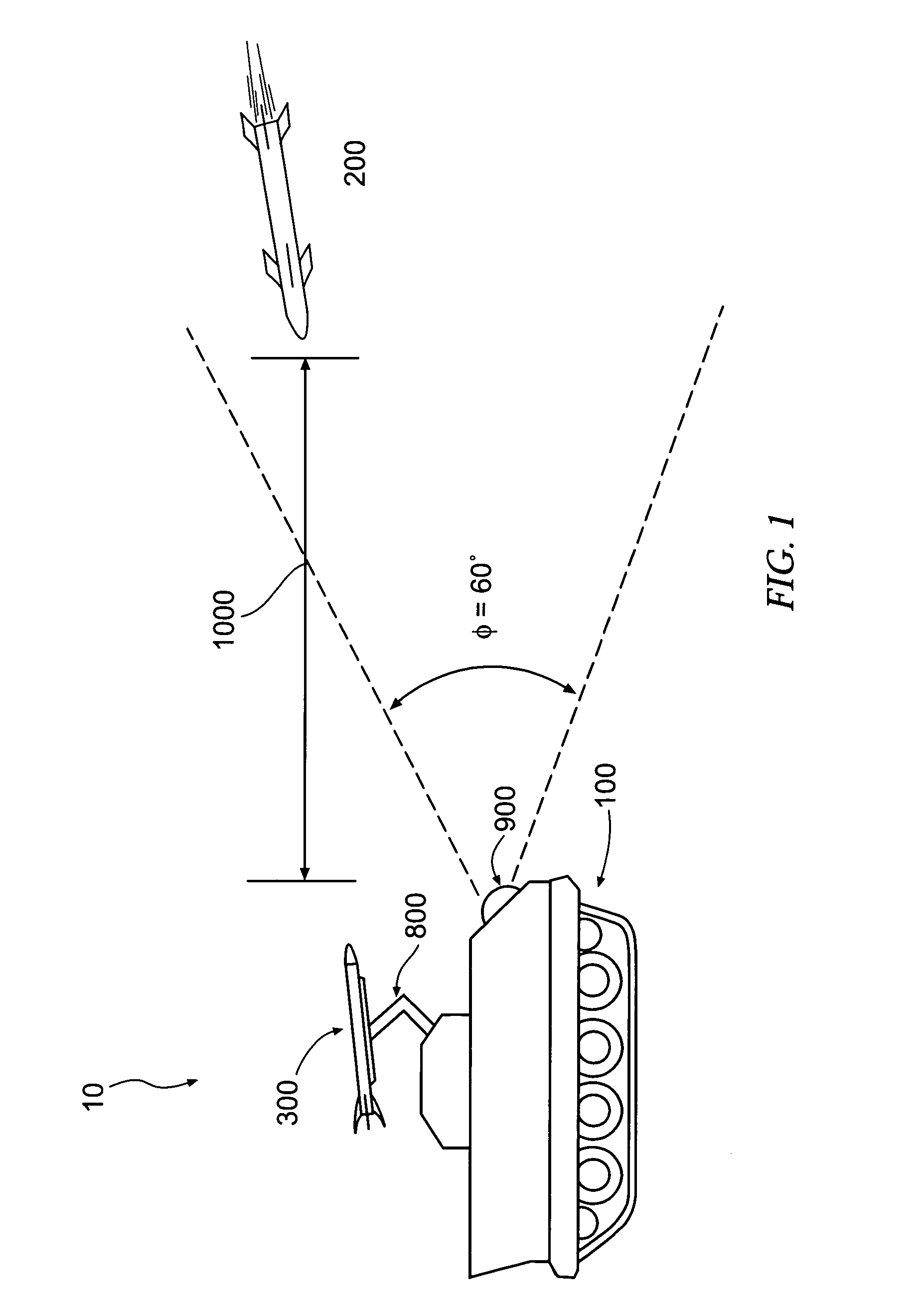
[0027]FIG. 1 illustrates an active protection system according to one embodiment of the present invention, the system being indicated generally by the numeral 10. Such a system 10, according to particularly advantageous embodiments of the present invention, is intended to protect a platform 100 against an incoming threat 200, wherein such a threat 200 may be, for instance, a chemical energy (CE) type or a kinetic energy (KE) type threat, as previously discussed, or any other type of threat 200 which may be address...


PUM


Abstract

An interceptor device for protecting a platform against an incoming threat is provided. The interceptor device comprises a housing and a countermeasure device. At least one detonating charge is capable of deploying the countermeasure device. A controller device housed by the housing is capable of directing the detonating charge(s) to deploy the countermeasure device at least partially radially outward of the housing, corresponding to the threat trajectory. A sensor device is in communication with the controller device, and comprises a range-finding apparatus including one of a LADAR, a RADAR, and a LIDAR device, capable of sensing the threat and / or a range thereof, at least partially radially outward of the housing, and notifying the controller device if the threat is sensed, to cause the controller device to direct the detonating charge(s) to deploy the countermeasure device to impact the threat in the intercept zone. Associated systems, and methods are also provided.

Description

CROSS-REFERENCES TO RELATED APPLICATIONS[0001]This application is a continuation-in-part of copending U.S. patent application Ser. No. 10 / 787,843, filed on Feb. 26, 2004, which is hereby incorporated herein in its entirety by reference.BACKGROUND OF THE INVENTION[0002]1. Field of the Invention[0003]The present invention relates to a defensive device and, more particularly, to an active protection device and associated apparatuses, systems, and methods.[0004]2. Description of Related Art[0005]High value strategic military platforms such as, for example, armored vehicles, amphibious assault vehicles, helicopters, gun boats, and the like, are subject to threats that can be generally categorized as follows:i. Gun-fired Kinetic Energy (KE) long rod penetrators that are very high in speed, on the order of about 5,000 ft / sec or more, and are capable of piercing armor.[0006]ii. Chemical Energy (CE) threats such as, for example, missiles and unguided rockets, including but not limited to Ant...

Claims


Application Information

Patent Timeline
Patent Type & Authority Patents(United States)
IPC IPC(8): F42B15/01F41G7/00G01S13/00
CPCF41H5/007F42B12/32F41H11/02
Inventor CHANG, YU-WEN
Owner CHANG IND INC
Why Eureka
Try Eureka