Spinal fixation system

a fixation system and spine technology, applied in the field of spine fixation devices, can solve the problems of limiting the range of motion of the spine, threatening the critical elements, and affecting the stability of the spine, and achieve the effect of increasing the locking strength and more uniform collaps

Active Publication Date: 2006-09-12
ZIMMER BIOMET SPINE INC
View PDF32 Cites 153 Cited by
  • Summary
  • Abstract
  • Description
  • Claims
  • Application Information

AI Technical Summary

Benefits of technology

[0009]It is another object of the present invention to provide a locking ball design for a spinal fixation clamp assembly that allows for more uniform collapse and thereby increases locking strength independent of the position of the ball.
[0010]It is another object of the present invention to provide a ball of a spinal clamp assembly that does not impinge on a contoured rod.

Problems solved by technology

Genetic or developmental irregularities, trauma, chronic stress, tumors, and disease, however, can result in spinal pathologies which either limit this range of motion, or threaten the critical elements of the nervous system housed within the spinal column.
While known spinal fixation systems have proven to be useful for various applications, they are all associated with drawbacks.
In this regard, the fixation screws or hooks of most known systems are difficult or impossible to adequately tighten to arrest relative movement between the anchors and support rod after implantation.
Overcoming this limitation typically involves a complex clamping arrangement or an arrangement that requires undue tightening.
Use of known systems are often a tedious process, which is inconsistent in result and adds unwanted time to a procedure.

Method used


Image

  • Spinal fixation system
  • Spinal fixation system
  • Spinal fixation system

Examples


Embodiment Construction

[0021]The following description of the preferred embodiments of the present invention is merely exemplary in nature and is in no way intended to limit the subject invention or its application or uses.

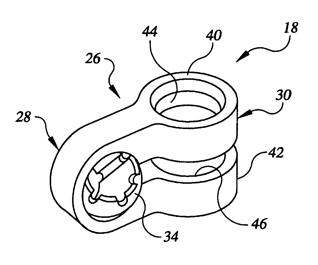
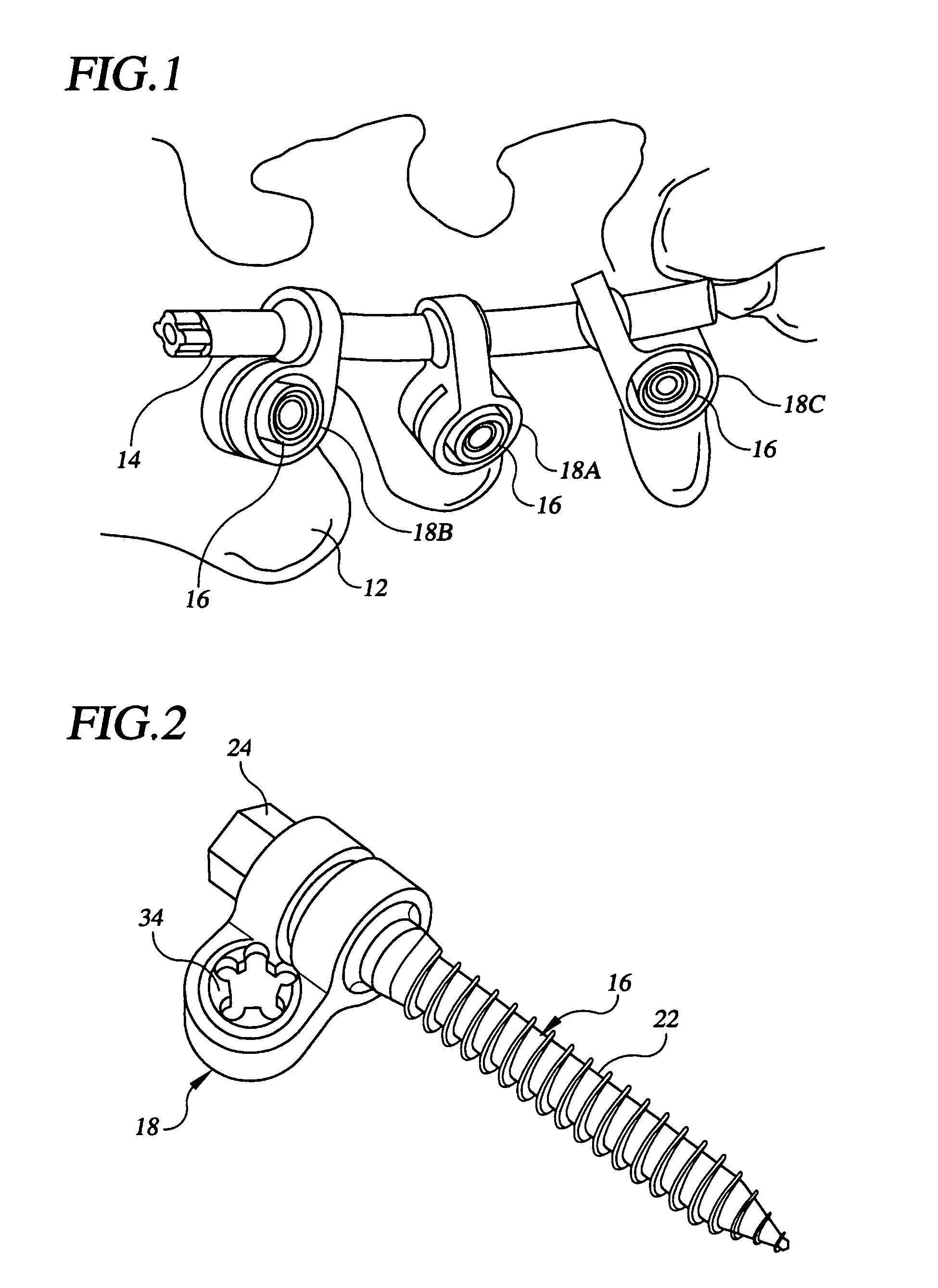
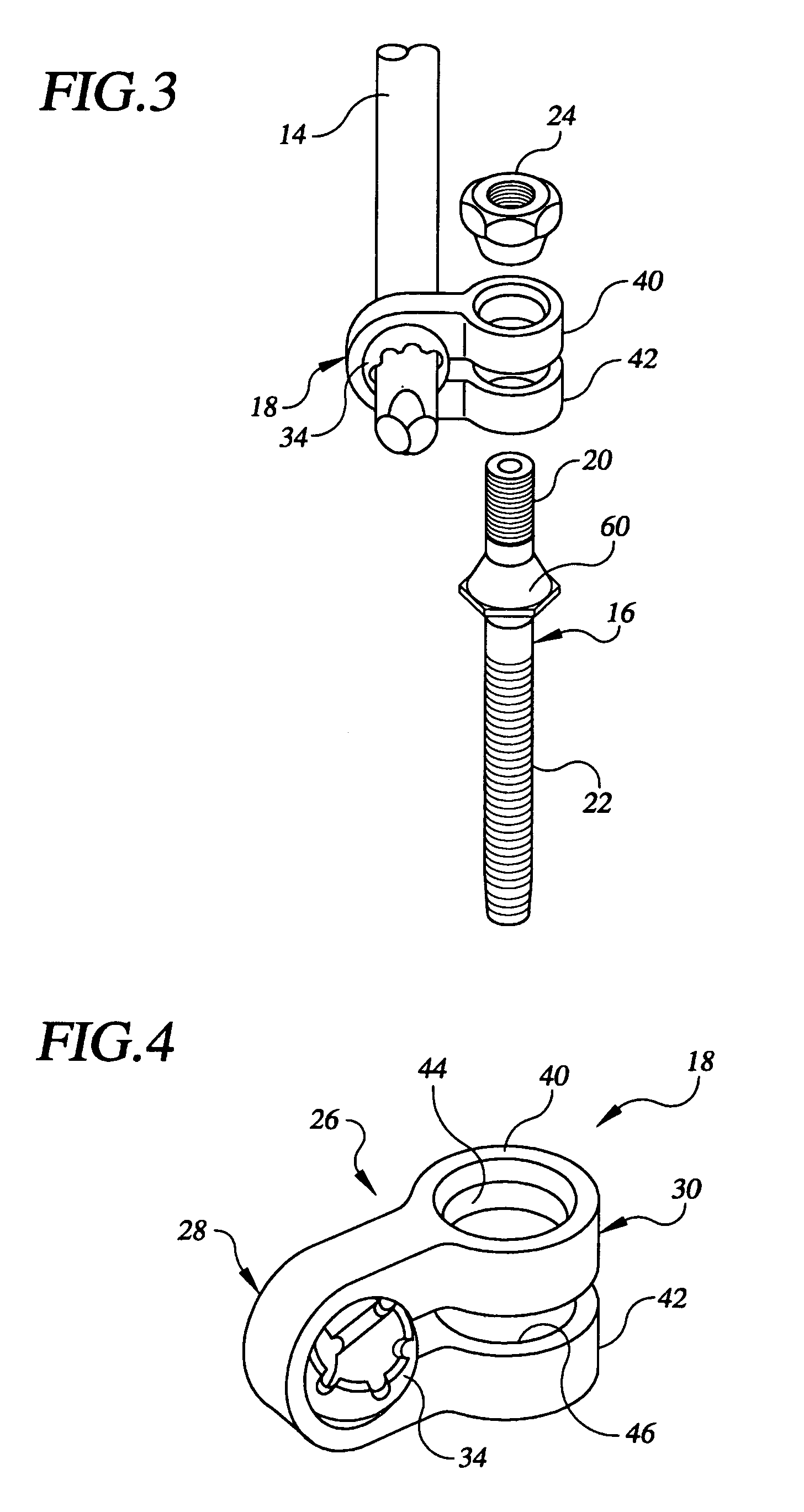
[0022]With general reference to the drawings, a spinal fixation system constructed in accordance with the teachings of the preferred embodiment of the present invention is illustrated and generally identified at reference character 10. As shown in the environmental view of FIG. 1, components of the system 10 have been arranged in an exemplary construct for attachment to a portion of a spinal column 12 of a human patient. The components of the system 10 of the present invention used in the construct of FIG. 10 generally include a linkage in the form of a generally cylindrical support rod 14, a plurality of spinal anchors 16 for engaging the spinal column 12, and a plurality of clamp assemblies 18 securing the spinal anchors 16 to the cylindrical rod 14.

[0023]The spinal anchors are illust...


PUM


Abstract

A spinal fixation system includes a rod, an anchor, and a clamp assembly. The anchor is adapted to engage a bone. The clamp assembly secures the anchor to the rod. The clamp assembly includes a first portion with first and second flanges for receiving the anchor. A compressible ball is carried by the second portion of the clamp assembly. The ball has a through hole receiving the rod. The through hole is defined by a generally cylindrical inner surface having at least one relieved channel. The first and second flanges include first and second opposing surfaces, respectively. The first and second opposing surfaces are normally angled relative to one another. A nut which threadably engages an upper shaft of the fastener is tightened to draw together the first and second flanges to a position in which they are generally parallel to one another. At least a portion of the through hole tapers from one of the first and second ends towards a center of the ball.

Description

FIELD OF THE INVENTION[0001]The present invention relates generally to the field of spinal fixation devices. More specifically, the present invention is directed to a clamp assembly of a spinal fixation system that couples a rod and a bone anchor.BACKGROUND OF THE INVENTION[0002]The spinal column is a highly complex structure which houses and protects critical elements of the nervous system. In spite of these complexities, the spinal column is a highly flexible structure, capable of a high degree of curvature and twist through a wide range motion. Genetic or developmental irregularities, trauma, chronic stress, tumors, and disease, however, can result in spinal pathologies which either limit this range of motion, or threaten the critical elements of the nervous system housed within the spinal column.[0003]A variety of systems has been disclosed in the art which achieve immobilization of portions of the spinal column by implanting artificial assemblies in or on the spinal column. The...

Claims


Application Information

Patent Timeline
Patent Type & Authority Patents(United States)
IPC IPC(8): A61B17/70
CPCA61B17/7041A61B17/7037A61B17/701A61B17/704
Inventor BAILEY, KIRK J
Owner ZIMMER BIOMET SPINE INC
Why Eureka
Try Eureka