Method for manufacturing photonic crystal fiber integrated end caps

A technology of photonic crystal fiber and fiber, which is applied in the field of fiber optics to achieve the effects of avoiding fiber surface damage and metal impurity sputtering pollution, low manufacturing cost, rapid and uniform collapse

Active Publication Date: 2017-05-10
SHANGHAI INST OF OPTICS & FINE MECHANICS CHINESE ACAD OF SCI
View PDF6 Cites 0 Cited by
  • Summary
  • Abstract
  • Description
  • Claims
  • Application Information

AI Technical Summary

Problems solved by technology

[0004] At present, there is no preparation technology that uses carbon dioxide laser to directly melt and collapse photonic crystal fibers to prepare integrated end caps.

Method used


Image

  • Method for manufacturing photonic crystal fiber integrated end caps
  • Method for manufacturing photonic crystal fiber integrated end caps
  • Method for manufacturing photonic crystal fiber integrated end caps

Examples


Embodiment 1

[0029] (1) Take a photonic crystal fiber with an outer diameter of 400 microns, an inner cladding of 200 microns, a core of 40 microns, an outer cladding air hole diameter of 12 microns, and an inner cladding air hole diameter of 2 microns, and first treat it with analytical pure alcohol The surface of the optical fiber, and then place the optical fiber in a standard optical fiber holder, and the distance from the optical fiber clamping position to the end face of the optical fiber is 10cm;

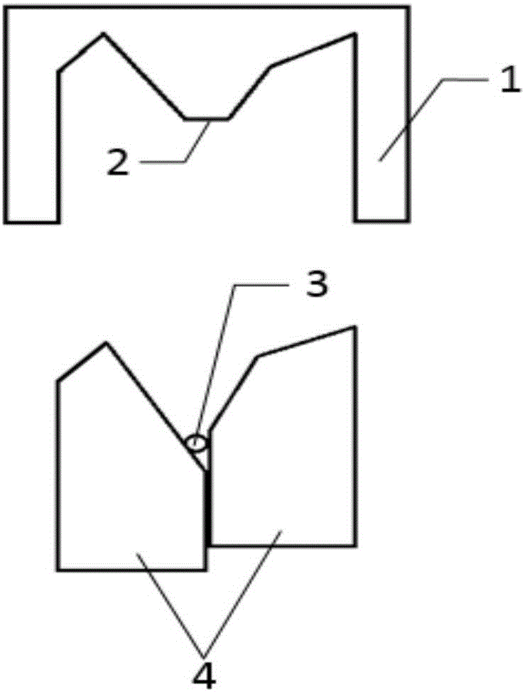
[0030] (2) Place the standard optical fiber clamp in the clamp slot of the optical fiber fusion splicer, place the optical fiber in the two V-shaped grooves of the optical fiber fusion splicer, and set the distance between the two V-shaped grooves to 4cm ; Make the self-made M-shaped V-groove cover (such as figure 1 shown), press down along the concave direction of the V-shaped groove, the flat-bottomed presser foot in the middle of the M-shaped V-shaped groove cover plate (such as figur...

Embodiment 2

[0036] (1) Take a photonic crystal fiber with an outer diameter of 400 microns, an inner cladding of 200 microns, a core of 40 microns, an outer cladding air hole diameter of 12 microns, and an inner cladding air hole diameter of 2 microns, and first treat it with analytical pure alcohol The surface of the optical fiber, and then place the optical fiber in a standard optical fiber holder, and the distance from the optical fiber clamping position to the end face of the optical fiber is 10cm;

[0037] (2) Place the standard optical fiber clamp in the clamp slot of the optical fiber fusion splicer, place the optical fiber in the two V-shaped grooves of the optical fiber fusion splicer, and set the distance between the two V-shaped grooves to 4cm ; Make the self-made M-shaped V-groove cover (such as figure 1 shown), press down along the concave direction of the V-shaped groove, the flat-bottomed presser foot in the middle of the M-shaped V-shaped groove cover plate (such as figur...

Embodiment 3

[0043](1) Take a photonic crystal fiber with an outer diameter of 570 microns, an inner cladding of 430 microns, a fiber core of 110 microns, an outer cladding air hole diameter of 15 microns, and an inner cladding air hole diameter of 3 microns, and first treat it with analytical pure alcohol The surface of the optical fiber, and then place the optical fiber in a standard optical fiber holder, and the distance from the optical fiber clamping position to the end face of the optical fiber is 10cm;

[0044] (2) Place the standard optical fiber clamp in the clamp slot of the optical fiber fusion splicer, place the optical fiber in the two V-shaped grooves of the optical fiber fusion splicer, and set the distance between the two V-shaped grooves to 4cm ; Make the self-made M-shaped V-groove cover (such as figure 1 shown), press down along the concave direction of the V-shaped groove, the flat-bottomed presser foot in the middle of the M-shaped V-shaped groove cover plate (such as ...


PUM

PropertyMeasurementUnit
lengthaaaaaaaaaa

Abstract

The invention discloses a method for manufacturing photonic crystal fiber integrated end caps. The method has the advantages that photonic crystal fibers with air holes are rotationally heated by the aid of carbon dioxide laser devices according to certain rotation speeds and heating power, the air holes can be uniformly synchronously collapsed and solidified, the photonic crystal fibers are further cut by fiber cutters, accordingly, the end caps with different end surface angles can be obtained, and application requirements on the large-mode-area photonic crystal fibers in the aspects of all-fiber laser devices and high-power laser can be met; the problem of insufficient weld strength due to uneven fiber cut sections when external quartz glass end caps and existing photonic crystal fibers are welded with one another can be solved, the seamlessly connected end caps can be obtained on the original photonic crystal fibers by means of direct collapsing, accordingly, follow-up treatment application can be facilitated, and the method is free of influence on the laser performance of the fibers.

Description

technical field [0001] The invention relates to an optical fiber, in particular to a method for preparing a quartz glass photonic crystal optical fiber end cap. Background technique [0002] Photonic crystal fiber (PCF) is widely used in optical communication, high power transmission, Fiber lasers, supercontinuum, etc. have broad applications. Its unique air hole structure makes it impossible to cut and splice like conventional silica fibers. Therefore, special processes must be used to treat the PCF end face, such as welding end caps, on the one hand to improve the pollution and end face damage caused by the temperature rise of the end face under high power conditions; Lay the foundation for all-fiber applications. Due to the particularity of PCF production and structure, the processing technology is difficult and expensive. Only a few companies such as NKT can complete the welding of end caps with high quality in the world. There is still a big gap between China and th...

Claims


Application Information

Patent Timeline
Patent Type & Authority Applications(China)
IPC IPC(8): G02B6/25
CPCG02B6/25
Inventor 张国栋于春雷冯素雅胡丽丽王孟
Owner SHANGHAI INST OF OPTICS & FINE MECHANICS CHINESE ACAD OF SCI
Why Eureka
Try Eureka