

Array substrate for dislay device and method of fabricating the same
- Summary
- Abstract
- Description
- Claims
- Application Information
AI Technical Summary
Benefits of technology
Problems solved by technology
Method used
Image

Examples
Embodiment Construction
[0042]Reference will now be made in detail to the embodiments of the present invention, examples of which are illustrated in the accompanying drawings. Wherever possible, similar reference numbers will be used to refer to the same or similar parts.
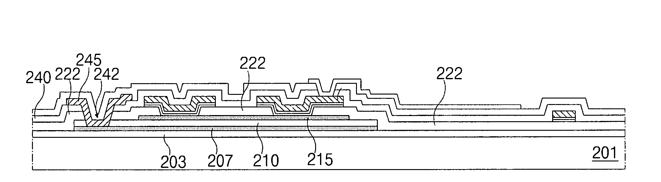
[0043]FIGS. 4A to 4M are cross-sectional views showing a method of fabricating an array substrate having a pixel region according to a first embodiment of the present invention, FIGS. 5A to 5M are cross-sectional views showing a method of fabricating an array substrate having a gate pad area according to a first embodiment of the present invention, and FIGS. 6A to 6M are cross-sectional views showing a method of fabricating an array substrate having a data pad area according to a first embodiment of the present invention.
[0044]In FIGS. 4A, 5A and 6A, a buffer layer 103 is formed on a substrate 101 having a pixel region P, a gate pad area GPA and a data pad area DPA by depositing an inorganic insulating material such as silicon oxide (SiO2)...
PUM
 Abstract
Description
Claims
Application Information