Radiation detector

a detector and radiation technology, applied in the field of radiation detectors, can solve the problems of severe practical restrictions on its use and the inability to meet practical requirements, and achieve the effect of satisfying practical requirements and severe practical restrictions

Inactive Publication Date: 2006-09-12
JAPAN SCI & TECH CORP
View PDF12 Cites 0 Cited by
  • Summary
  • Abstract
  • Description
  • Claims
  • Application Information

AI Technical Summary

Benefits of technology

[0006]This invention solves the above-mentioned problem, and provides a radiation detector using a scintillator having a large luminescence intensity and a short time constant.

Problems solved by technology

Among scintillators in practical use, barium fluoride is unique in having a decay time constant (600 picoseconds) of subnanosecond order (M. Laval, M. Moszynski, R. Allemand, E. Cormoreche, P. Guinet, R. Odru and J. Vacher, Nucl. Instru. Meth., 206 (1983) 169), but as its luminescence wavelength is in the ultraviolet region, there are severe practical restrictions to its use.
For example, GSO(Ce) has an intermediate luminescence intensity and an intermediate time constant (60 nanoseconds), but its performance does not satisfy practical requirements (Carel W. E van Eijk, “Nuclear Instruments & Method in Physics Research Section A—Accelerators Spectrometers Setectors and Associated Equipment” Nucl. Instr. and Meth.

Method used


Image

  • Radiation detector
  • Radiation detector
  • Radiation detector

Examples


example 1

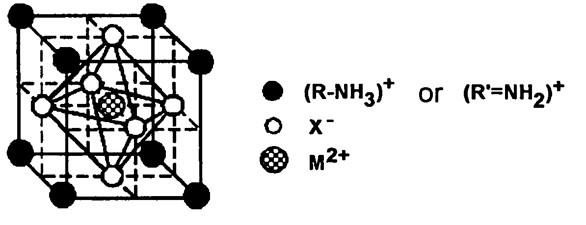
[0034]60.22 g hydrobromic acid (HBr, Wako Pure Chemicals, concentration 0.48) was introduced in a 200 ml flask at room temperature, and 27.06 g of 40% aqueous methylamine solution (Wako Pure Chemicals, concentration 0.41) was gradually dripped in. As this is an exothermic reaction, the flask was placed in a water bath. Methylamine was dripped until the molar ratio of hydrobromic acid, HBr, to methylamine, CH3NH2, was 1:1. After addition was complete, the mixture was left with stirring for 1 hour to complete the reaction, and a colorless, transparent aqueous solution of methylamine bromide was thus obtained. When water was removed on an evaporator (water bath temperature 45° C.), a white powder of methylamine bromide remained. This was washed by diethyl ether (suction filtration), and after removing unreacted material, it was dried. The yield was 35.98 g, i.e., 90.0%.

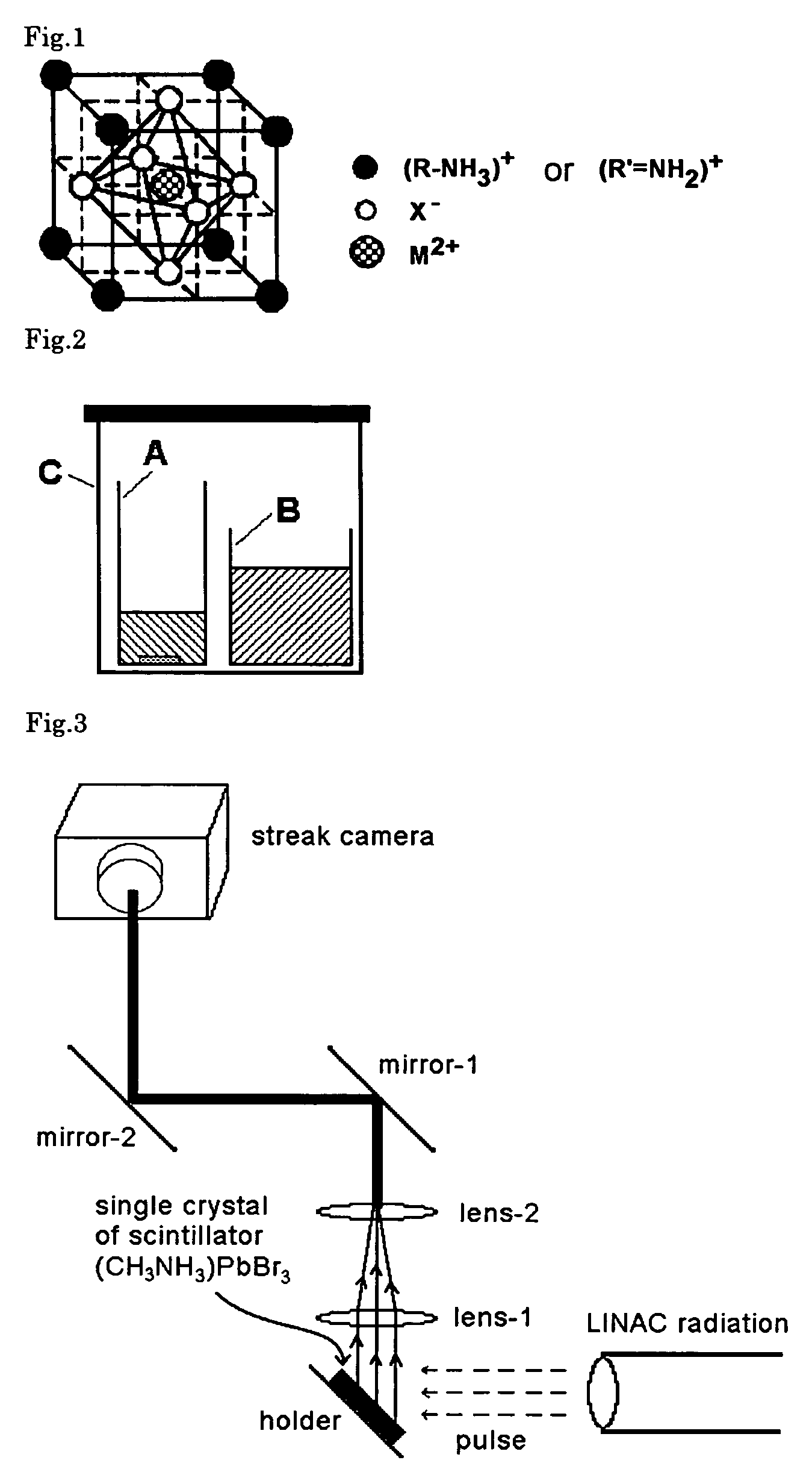
[0035]Next, 18.8 g of the methylamine bromide obtained as mentioned above was dissolved in 100 ml DMF in a 200 ml thre...

example 2

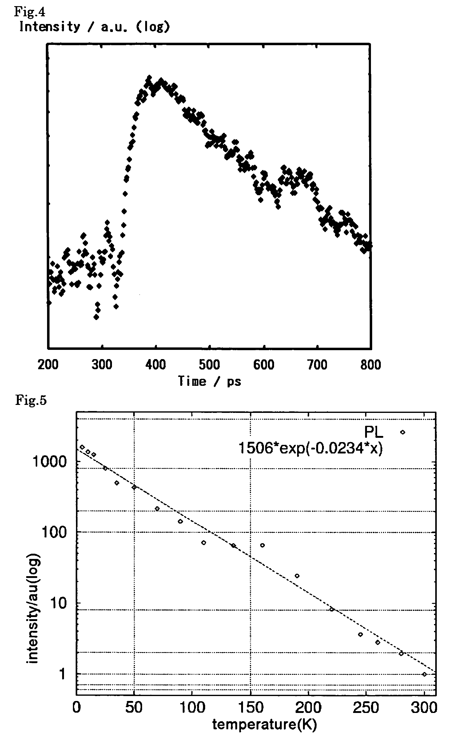
[0039]While varying the temperature of the single crystals manufactured in Example 1, a scintillation luminescence spectrum from the sample was measured by irradiating it with hydrogen ions of 2.0 MeV using a Van der Graaf accelerator (Tokyo University Atomic Energy Research Center). The measurement result showed an identical relation to the relation between luminescence intensity due to irradiation with ultraviolet light (He—Cd laser), and temperature.

[0040]The result of irradiation with ultraviolet light is shown in FIG. 5. Taking the reference value of luminescence intensity for NaI(Tl) as 100, the luminescence intensity of this compound at 300K was 0.075, and at 25K was 140. The luminescence intensity decreases exponentially as a function of the absolute temperature.

example 3

[0041]In this example, the single crystal manufactured in Example 1 was irradiated with γ-rays, and it was confirmed that this single crystal could detect the γ-rays.

[0042]A schematic view of the system used in this test is shown in FIG. 6. 22Na was the sealed source of the γ-rays, and the intensity was 370 Bq (Becquerels). The single crystal was sealed in a cryostat cold finger, and cooled to 40K. The luminescence was directly received by a PMT (photomultiplier, Phillips, XP4222B) attached to a quartz glass window. The signal from the PMT was amplified by an AMP, and recorded as an energy spectrum by an MCA (wave height discrimination machine). The result is shown in FIG. 7.

[0043]In FIG. 7, the solid line shows the signal intensity when the single crystal was installed and cooled to 40K. On the other hand, the black shaded part shows the noise level for the signal intensity when there is no scintillator crystal. From the difference, it can be seen that the single crystal emits a sc...


PUM

PropertyMeasurementUnit
wavelengthaaaaaaaaaa
temperatureaaaaaaaaaa
PETaaaaaaaaaa

Abstract

This invention provides a radiation detector using a scintillator having both a strong luminescence intensity and a short time constant. The radiation detector comprises as a scintillator an organic / inorganic perovskite hybrid compound represented by the general formula AMX3, wherein A is R—NH3 or R′—NH2, or a mixture thereof, R is a hydrogen atom or a methyl group which may be substituted by an amino group or a halogen atom, R′ is a methylene group which may be substituted by an amino group or a halogen atom, each X is a halogen atom that may be identical to or different from the other X groups, and M is a Group IVa metal, Eu, Cd, Cu, Fe, Mn or Pd.

Description

TECHNICAL FIELD OF THE INVENTION[0001]This invention relates to a radiation detector for ionizing radiations, such as γ-rays, X-rays, electron beams, heavy charged particle beams and neutron beams, and more specifically, having a very short time from a rise to a disappearance of luminescence of subnanosecond order.PRIOR ART[0002]A scintillator detects and measures ionizing radiation optically by using a solid radiation relaxation phenomenon. In recent years, in fields such as physics, chemistry, biology and medicine, the use of short-pulsed radiation is becoming more widespread and simple methods of measuring short-pulsed radiation are required. For example, in the case of a PET (positron emission tomography) which is a medical device, the time resolution of the scintillator is directly linked to the spatial resolving power of the system, so the higher the resolving power of the scintillator is, the more precise the diagnosis that can be performed. There is therefore a demand for a ...

Claims


Application Information

Patent Timeline
Patent Type & Authority Patents(United States)
IPC IPC(8): C09K11/08C09K11/06G01T1/00C09K11/66G01T1/161G01T1/20
CPCC09K11/06C09K11/664C09K2211/188
Inventor SHIBUYA, KENGOKOSHIMIZU, MASANORITAKEOKA, YUKOASAI, KEISUKI
Owner JAPAN SCI & TECH CORP
Why Eureka
Try Eureka