Light source device and illumination device including the light source device

a technology of illumination device and light source, which is applied in the direction of semiconductor devices, lighting and heating equipment, fixed installations, etc., can solve the problems of unpleasant brightness called “glare”, cannot be used for indoor illumination device, and cannot be modified, etc., and achieves large luminescence intensity, large size, and strong directionality

Inactive Publication Date: 2015-06-23
OPTO DESIGN INC
View PDF9 Cites 0 Cited by
  • Summary
  • Abstract
  • Description
  • Claims
  • Application Information

AI Technical Summary

Benefits of technology

[0009]The light source device disclosed in each of Patent Documents 1 to 3 described above spreads the light from the point source in a planar manner and uniformizes the light emitted from a light irradiation surface through multiple reflection on the reflective plate disposed in the light emission direction of the LED, the bottom portion to which the LED is fixed, and the sidewall portion. However, thinning the illumination device reduces a distance between the LED of the light source device and the reflection means. In addition, depending on the material of the reflection means, the reflection means located directly above the LED absorbs more a particular wavelength of the light from the LED, thereby causing uneven colors to occur in the surrounding part. This poses a limitation in reducing the distance between the LED and the reflection means.
[0012]With the light source device of the first aspect of the present invention, the emission side reflective plate is formed so that the portion thereof facing the light source has the highest optical reflectance and the lowest optical transmittance while the optical reflectance decreases and the optical transmittance increases as being farther away from the light source. Therefore, uniform illumination light can be obtained from the whole surface of the emission side reflective plate although an LED is used as the light source. The distance between the light source side reflective plate and the emission side reflective plate is greatest at the portion where the light source is disposed. Thus, uneven colors are less likely to occur. At the same time, the distance between the light source side reflective plate and the emission side reflective plate decreases as being farther away from the portion where the light source is disposed, and is smallest at a circumferential edge portion of the illumination device. This can give visually thinner impression.
[0014]With the light source device of the second aspect of the present invention, light emitted from the light source is also output through the gap provided between the light source side reflective plate and the emission side reflective plate at the outer edge portion of the light source device. This prevents the outer edge portion from being dark, and provides more uniform illumination light.
[0016]With the light source device of the third aspect of the present invention, the light source side reflective plate and the emission side reflective plate are fixed without a gap therebetween. This can provide the light source device that gives a thinner impression at the outer edge portion thereof.
[0018]The light source device of the present invention can achieve the particular functions and effects described above even with the emission side reflective plate exposed. However, using the diffusion plate having a light scattering effect can provide the illumination light having a more uniform illuminance distribution.
[0022]The LED is a known point source of light having strong directionality and a large luminescence intensity. However, with the light source device and the illumination device of the present invention, using the light source including the light-emitting diodes arranged in a strip-like or ring-like manner can provide an illumination device that is brighter while having a large size.

Problems solved by technology

The planar light sources that are used for indoor illumination devices and the like are required to emit light uniformly, but since LEDs have strong light directionality, they are not suitable, without modification, to be used for indoor illumination devices.
The strong-directionality light of LEDs causes unpleasant brightness called “glare” when it enters eyes directly.

Method used


Image

  • Light source device and illumination device including the light source device
  • Light source device and illumination device including the light source device
  • Light source device and illumination device including the light source device

Examples


first embodiment

[0037][First Embodiment]

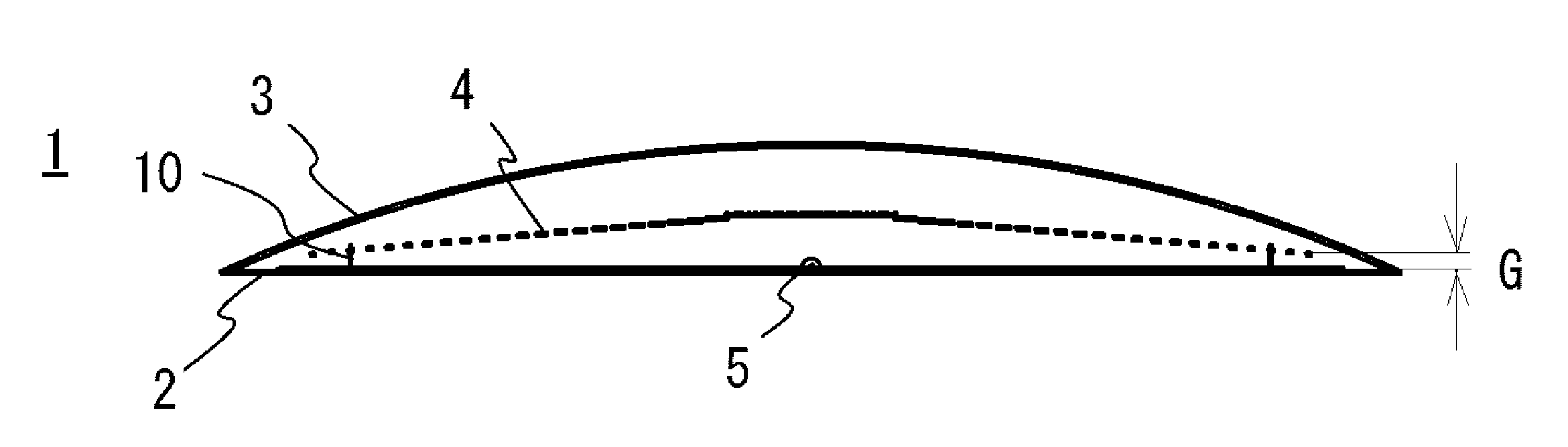
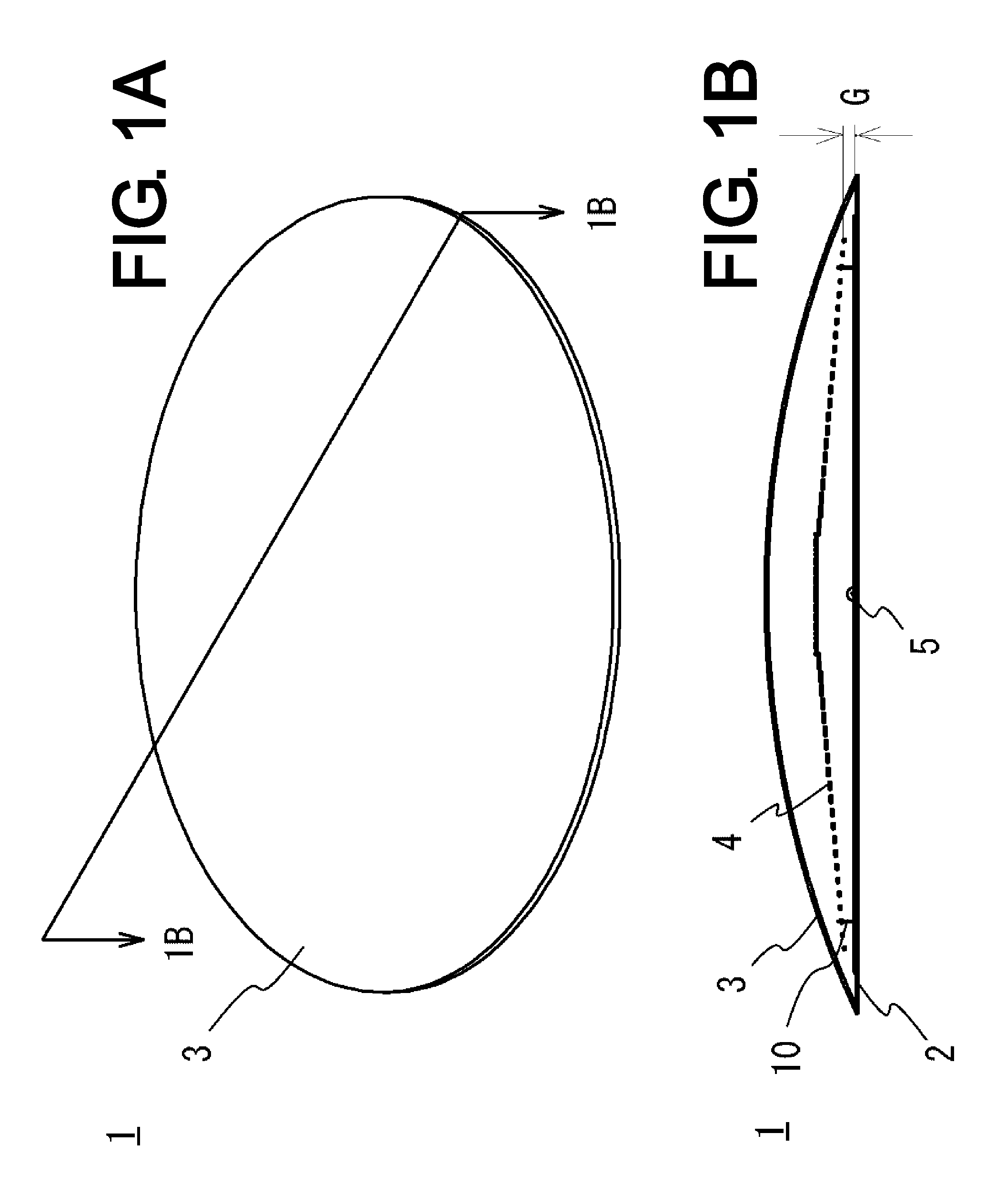
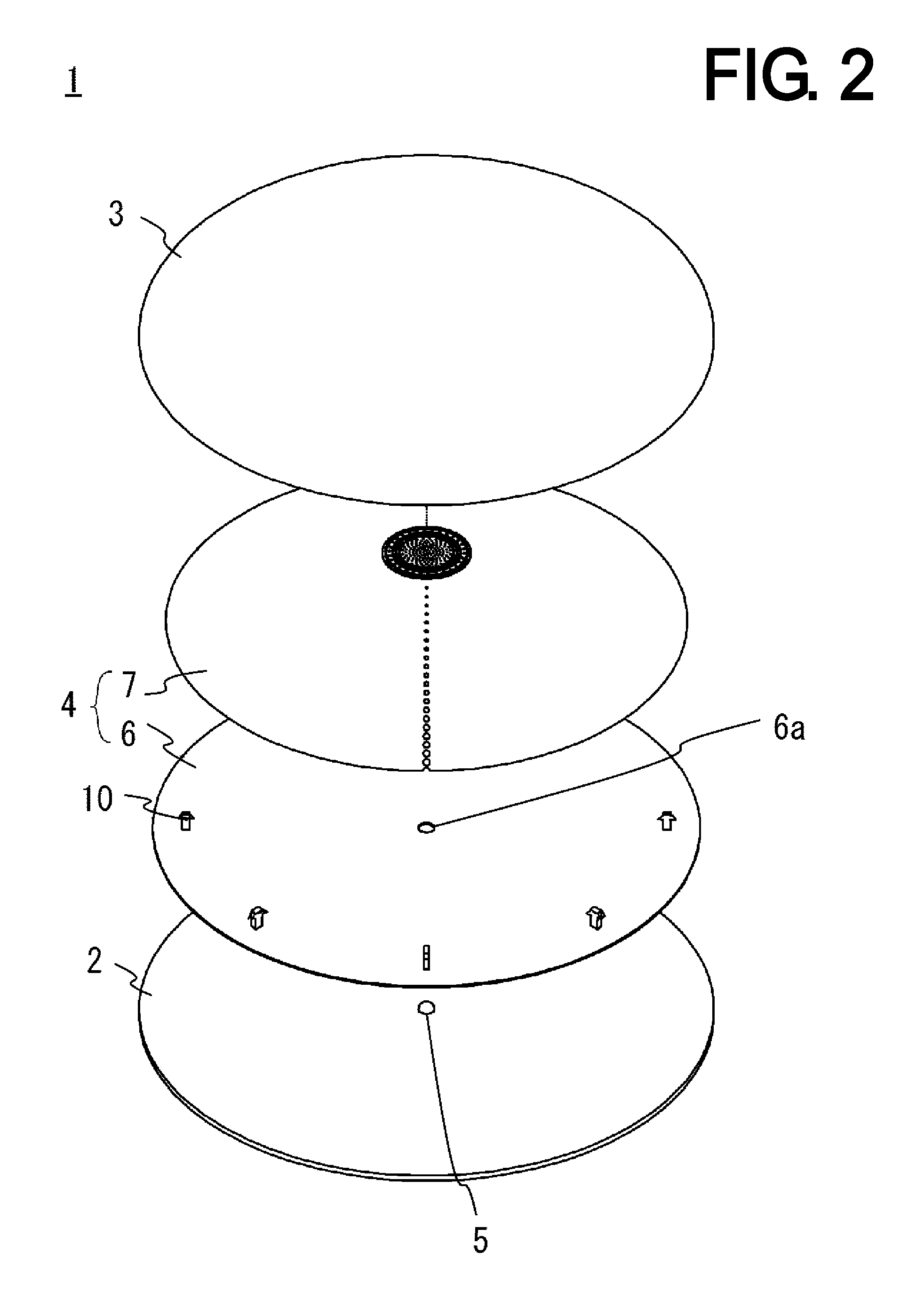
[0038]An illumination device according to a first embodiment of the present invention will be described using FIGS. 1A to 4. FIG. 1A is a perspective view of the illumination device according to the first embodiment of the present invention; FIG. 1B is a sectional view along 1B-1B line of FIG. 1A; FIG. 2 is an exploded perspective view of the illumination device of FIG. 1A; FIG. 3 is a plan view of an emission side reflective plate of the illumination device of FIG. 1A; and FIG. 4 is a development view of the emission side reflective plate of FIG. 3.

[0039]As illustrated in FIGS. 1A, 1B, and 2, this illumination device 1 according to the first embodiment includes a flat plate-like frame body 2, a light source device 4 fixed to the frame body 2, and a dome-like diffusion plate 3 that is mounted so as to cover the frame body 2 and the light source device 4.

[0040]The frame body 2 is formed of metal plate material or a synthetic resin formed body, and has a disk-l...

second embodiment

[0055][Second Embodiment]

[0056]An illumination device according to a second embodiment of the present invention will be described using FIGS. 5A, 5B, and 6. FIG. 5A is a perspective view of the illumination device according to the second embodiment of the present invention; FIG. 5B is a sectional view along VB-VB line of FIG. 5A; and FIG. 6 is an exploded perspective view of the illumination device of FIG. 5A.

[0057]In this illumination device 1A according to the second embodiment, a part of the configuration differs from that of the illumination device 1 according to the first embodiment whereas the other part thereof is in common with that of the illumination device 1. Thus, a suffix “A” will be added to the same reference numerals in the common parts, and detailed description thereof will be omitted. As illustrated in FIGS. 5A, 5B, and 6, the illumination device 1A does not include the frame body of the illumination device 1 according to the first embodiment, and includes a light ...

third embodiment

[0062][Third Embodiment]

[0063]A light source device according to a third embodiment of the present invention will be described using FIGS. 7 to 9. FIG. 7 is a perspective view of the light source device according to the third embodiment of the present invention; FIG. 8 is an exploded perspective view of the light source device of FIG. 7; and FIG. 9 is a plan view of an emission side reflective plate of the light source device of FIG. 8. In FIGS. 7 to 9, the illumination device does not include a diffusion plate or a frame body.

[0064]An illumination device 1B according to the third embodiment of the present invention differs from the illumination device 1 according to the first embodiment in the shape of the light source device 4 and the arrangement of a light source 5B whereas the other part is in common with the illumination device 1. Thus, for the common part, illustrations will be omitted, a suffix “B” will be added to the same reference numerals, and detailed description thereof...


PUM


Abstract

An illumination device including a light source device includes a light source being constituted by LED(s); a light source side reflective plate to which the light source is fixed; an emission side reflective plate facing the light source side reflective plate; and a fixing means for fixing the both reflective plates, wherein the emission side reflective plate is formed so that a portion thereof facing the light source has the highest optical reflectance and the lowest optical transmittance while the optical reflectance decreases and the optical transmittance increases farther away from the light source, and the distance between the both reflective plates is greatest at a portion where the light source is disposed, while the distance decreases at portions farther away from the portion where the light source is disposed. Thus the device can supply light in a substantially uniform manner from a light irradiation surface.

Description

TECHNICAL FIELD[0001]The present invention relates to an illumination device, and more particularly to an illumination device that is thin and can illuminate a light irradiation surface in a substantially uniform manner using a light-emitting diode as a light source.BACKGROUND ART[0002]Over recent years, research and development of light-emitting diodes (hereinafter referred as to “LEDs”) have been advancing at a rapid pace, with various types of LEDs being developed, productized, and used in a wide range of fields. Due to their features of low power consumption, long life, and compactness, LEDs have long been much used as operation indicator lights for electronic equipment and the like. These LEDs have been used in, for example, backlights for liquid crystal panels, various kinds of display boards, electronic signboards, decorative illumination devices and so forth, and have now come to be used in the field of illumination. In the illumination field, they are used for automobile he...

Claims


Application Information

Patent Timeline
Patent Type & Authority Patents(United States)
IPC IPC(8): F21V7/00F21V13/10
CPCF21V7/0025F21V13/10F21V7/0041F21S8/033F21S8/04F21V11/14F21V17/164F21Y2103/10F21Y2115/10F21Y2103/33
Inventor SATO, EIICHISATO, KENSATO, HIROYASU
Owner OPTO DESIGN INC
Why Eureka
Try Eureka