Optical unit

a technology of optical units and optical components, applied in the field of optical units, to achieve the effect of increasing the maximum luminous intensity, increasing the size of the illumination region, and increasing the illumination area

Active Publication Date: 2022-07-14
KOITO MFG CO LTD
View PDF4 Cites 0 Cited by
  • Summary
  • Abstract
  • Description
  • Claims
  • Application Information

AI Technical Summary

Benefits of technology

[0011](2) Another exemplary object of the present invention is to provide a novel technique that can increase the maximum luminous intensity while increasing the size of the illumination region of a light distribution pattern.
[0012](3) Another exemplary object of the present...

Problems solved by technology

However, since the plurality of lens portions are located close to each other, some of the light emitted from one light emitting modul...

Method used


Image

  • Optical unit
  • Optical unit
  • Optical unit

Examples


first embodiment

[0081]An optical unit that includes a lens unit according to the present embodiment can be used in various vehicle lamps. First, an overview of a vehicle headlamp to which the optical unit according to the embodiment described later can be mounted will be given.

(Vehicle Headlamp)

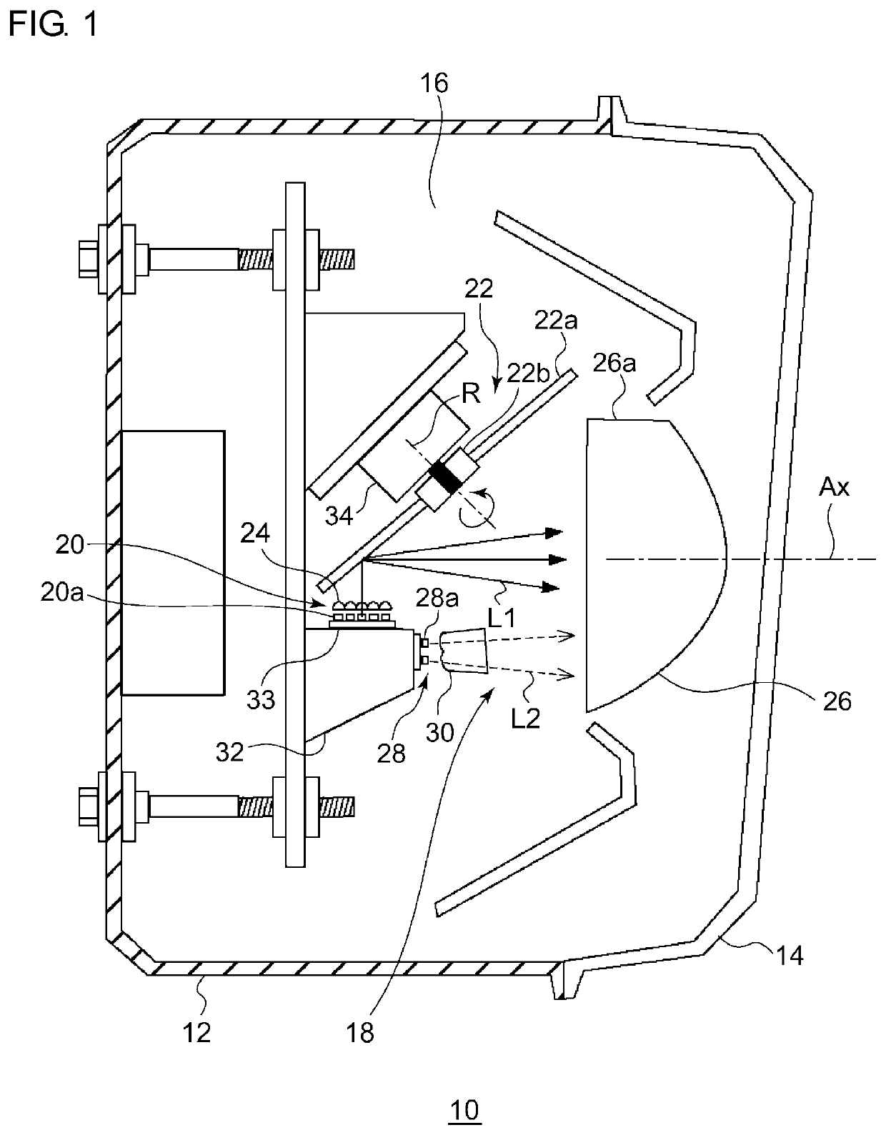
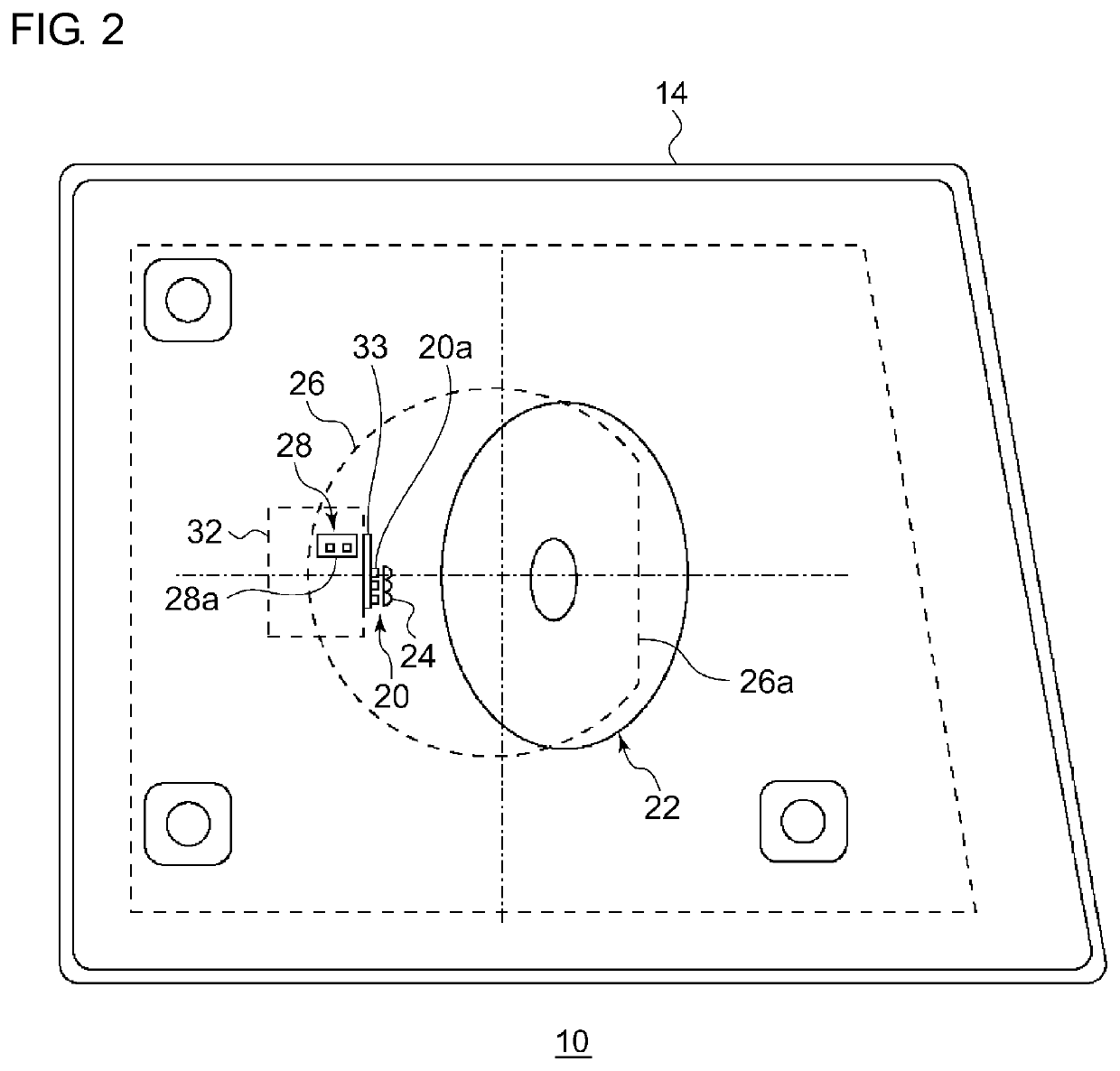
[0082]FIG. 1 is a schematic horizontal sectional view of a vehicle headlamp according to the present embodiment. FIG. 2 is a front view of the vehicle headlamp according to the present embodiment. FIG. 2 omits some of the components.

[0083]A vehicle headlamp 10 according to the present embodiment is a right-side headlamp to be mounted in a front right part of an automobile and has a structure identical to the structure of a headlamp to be mounted in the left side except that these headlamps are horizontally symmetric. Therefore, the right-side vehicle headlamp 10 will be described below in detail, and the description of the left-side vehicle headlamp will be omitted.

[0084]As illustrated in FIG. 1, the vehicle...

second embodiment

(Vehicle Headlamp)

[0109]FIG. 8 is a schematic horizontal sectional view of a vehicle headlamp according to the present embodiment. FIG. 9 is a front view of the vehicle headlamp according to the present embodiment. FIG. 9 omits some of the components. The vehicle headlamp according to the present embodiment illustrated in FIGS. 8 and 9 differs from the vehicle headlamp according to the first embodiment in that two LEDs 28a of the second light source 28 are disposed in an array and next to each other in the vertical direction. Thus, the detailed description of the vehicle headlamp illustrated in FIGS. 8 and 9 will be omitted.

(Light Distribution Pattern)

[0110]FIG. 10 schematically illustrates optical paths of exit lights in an optical unit according to the present embodiment. FIG. 11 is a schematic diagram looking in the direction of the arrow B indicated in FIG. 10. FIG. 12 is a schematic diagram of a light distribution pattern formed by the optical unit according to the present embo...

third embodiment

(First Light Source)

[0122]Next, a layout of a plurality of semiconductor light emitting elements included in a first light source will be described. FIG. 13 is a top view of a circuit board according to the present embodiment. The circuit board 33 according to the present embodiment has mounted thereon eight LEDs 20a1 (20a) that illuminate a region including the H-H line of a high-beam light distribution pattern and two LEDs 20a2 (20a) that illuminate a region above the H-H line. The up, down, front, and back directions indicated in FIG. 13 are defined with the direction of the optical axis Ax of the vehicle headlamp 10 regarded as the front direction.

(Optical Member)

[0123]Next, an optical member according to the present embodiment will be described. FIG. 14 is a perspective view of the optical member according to the present embodiment. FIG. 15 is a front view of the optical member according to the present embodiment. FIG. 16 is a rear view of the optical member according to the pr...


PUM


Abstract

An optical unit includes a first light source, a second light source, a rotary reflector that rotates about an axis of rotation while reflecting first light emitted from the first light source, and a projection lens that projects the first light reflected by the rotary reflector into a light illuminating direction of the optical unit to form a first light distribution pattern. The second light source is disposed such that second light emitted from the second light source enters the projection lens without being reflected by the rotary reflector. The projection lens is configured to project the second light into the light illuminating direction of the optical unit to form a second light distribution pattern such that the second light distribution pattern overlaps an end portion of the first light distribution pattern in a right-left direction.

Description

BACKGROUND1. Field of the Invention[0001]The present invention relates to optical units.2. Description of the Related Art[0002]In one device devised in recent years, light emitted from a light source is reflected toward a space in front of a vehicle, and this reflected light scans a region in front of the vehicle to form a predetermined light distribution pattern. For example, there is known an optical unit that includes a light source constituted by a light emitting element and a rotary reflector that rotates in one direction about an axis of rotation while reflecting light emitted from the light source. The rotary reflector is provided with a reflective surface such that the light emitted from the light source and reflected by the rotating rotary reflector forms a desired light distribution pattern (see patent document 1).[0003]This optical unit includes a first light source, a second light source, a rotary reflector that rotates about an axis of rotation while reflecting first li...

Claims


Application Information

Patent Timeline
IPC IPC(8): F21S41/675F21S41/148G02B26/08
CPCF21S41/675G02B26/0816F21S41/148F21S41/265F21S41/151F21S41/143F21S41/275F21S41/663G02B3/08G02B17/086G02B27/0933G02B27/0922
Inventor SAKURAI, KAZUTOSHITANAKA, HIDETADA
Owner KOITO MFG CO LTD
Why Eureka
Try Eureka