
Alarm device for use with fall protection equipment

an alarm device and fall protection technology, applied in the direction of safety belts, instruments, sport apparatus, etc., can solve the problems of workers getting caught on obstructions, using motorized tugger lines, serious injury or death, etc., and achieve the effect of increasing the length of the cabl

Active Publication Date: 2006-09-12
D B IND
View PDF11 Cites 46 Cited by
  • Summary
  • Abstract
  • Description
  • Claims
  • Application Information

AI Technical Summary

Benefits of technology

The alarm device effectively alerts operators to potential hazards, allowing for timely intervention to prevent injuries by sounding an alarm and visually indicating the issue, thereby reducing the risk of serious harm to workers.

Problems solved by technology

A risk of using motorized tugger lines is the possibility of workers getting caught on obstructions such as the oil derrick structure or other structures as the workers are being raised and / or lowered by the tugger lines.
If a worker gets caught on an obstruction, the tugger continues to pull the tugger line thereby continuing to pull the worker, which could result in serious injury or death.
However, even with “man-rated” tuggers having such a built-in safety precaution, the “man-rated” tuggers may actually provide a false sense of security and may still have risks of serious injury or death should workers get caught on obstructions.
Typical “man-rated” tuggers lift from approximately 1,000 to 40,000 pounds, which is questionable for safety purposes.
Should a worker fall, the worker may need to be rescued, especially if the worker has been injured during the fall.
Therefore, timely rescue may be critical.

Method used


Image

  • Alarm device for use with fall protection equipment
  • Alarm device for use with fall protection equipment
  • Alarm device for use with fall protection equipment

Examples


Embodiment Construction

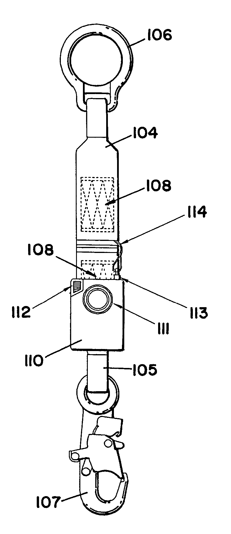
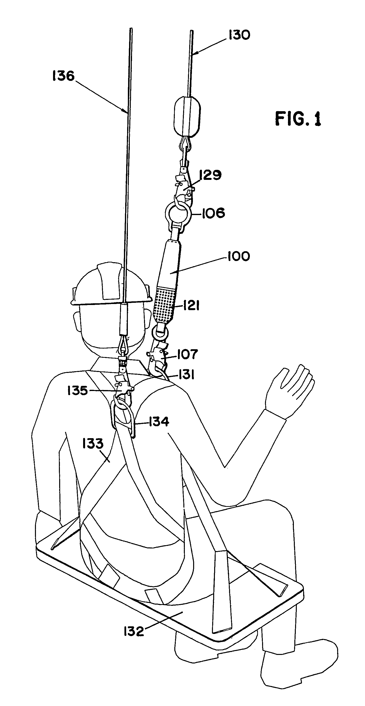
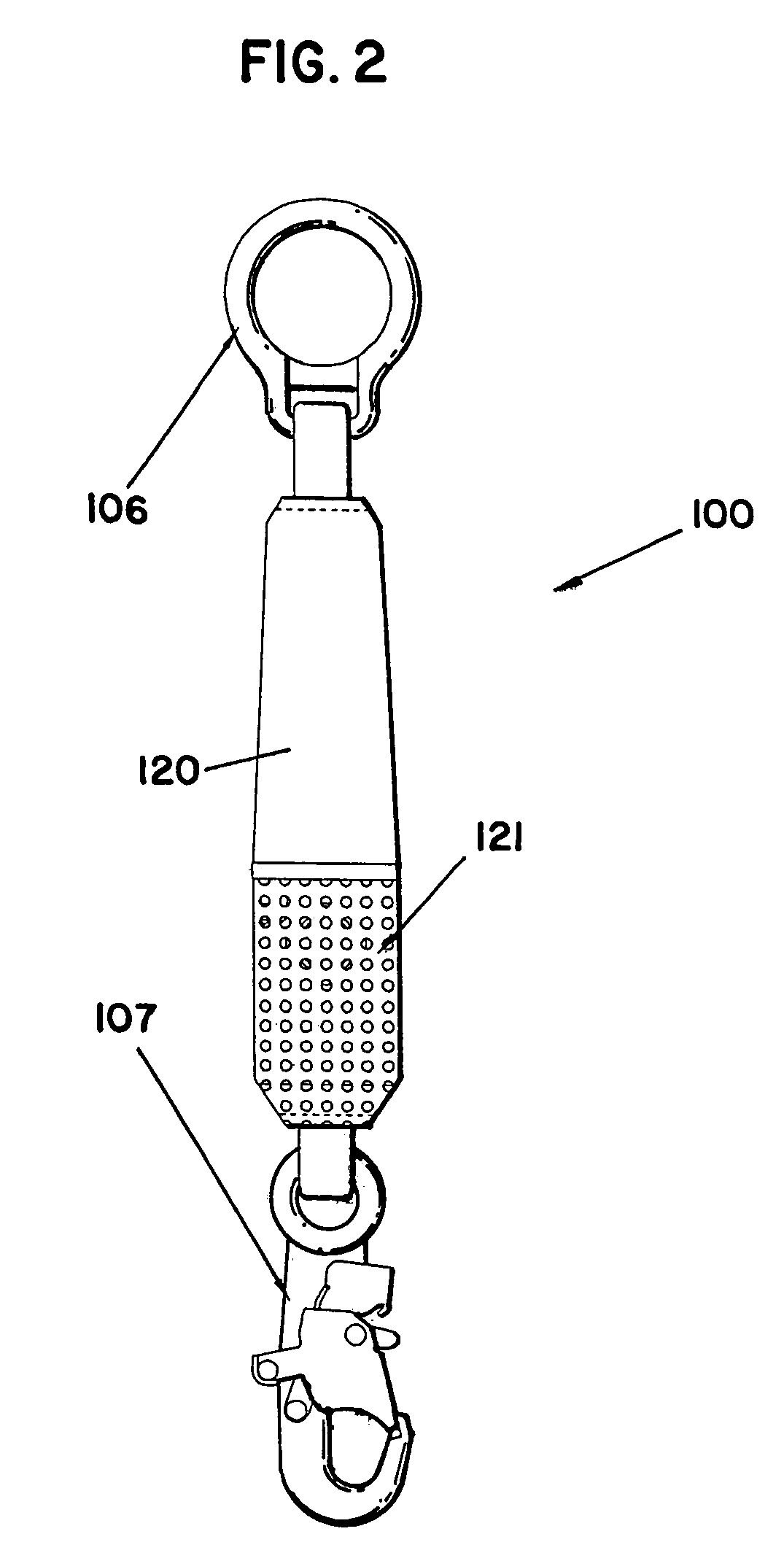
[0021]The present invention may be used in many different fall protection applications. A preferred embodiment load limiting alarm device constructed according to the principles of the present invention is designated by the numeral 100 in the drawings. A preferred embodiment shock absorbing alarm device constructed according to the principles of the present invention is designated by the numeral 200 in the drawings.

[0022]In one possible application of the present invention, the load limiting alarm device 100 includes an elongating member 101, which is preferably made of webbing having a first end 104 and a second end 105 interconnected with an interconnected portion 109 formed by a first ply 102 interwoven with a second ply 103. The interconnected portion 109 is preferably made of double needle loom webbing that may be torn apart and partially to completely separated into the first ply 102 and the second ply 103 to lengthen the distance between the first end 104 and the second end 1...


PUM


Abstract

A preferred embodiment alarm device for use with fall protection equipment includes an elongating member, an alarm, an activation member, and a connecting member. The elongating member has a first end and a second end and extends in length as the first end and the second end are pulled in different directions. The alarm is operatively connected to the first end of the elongating member, and the activation member is releasably connected to the alarm. The activation member activates the alarm when disconnected from the alarm. The connecting member interconnects the activation member and the second end of the elongating member, and the activation member becomes disconnected from the alarm when the elongating member is extended in length as the first end and the second end are pulled in different directions thereby activating the alarm when the elongating member is extended.

Description

BACKGROUND OF THE INVENTION[0001]1. Field of the Invention[0002]The present invention relates to an alarm device for use with fall protection equipment.[0003]2. Description of the Prior Art[0004]With regard to one possible application of the present invention, motorized tugger lines (winch lines on hoists commonly referred to as tuggers) are commonly used in the petroleum drilling industry to raise and / or lower equipment and / or workers up to and down from a derrick. A derrick is a framework over a drill hole (as of an oil well) for supporting boring tackle and / or for hoisting and lowering equipment and / or workers. Commonly, a worker will sit on a boatswain chair connected to the tugger line.[0005]A risk of using motorized tugger lines is the possibility of workers getting caught on obstructions such as the oil derrick structure or other structures as the workers are being raised and / or lowered by the tugger lines. If a worker gets caught on an obstruction, the tugger continues to pu...

Claims


Application Information

Patent Timeline
Patent Type & Authority Patents(United States)
IPC IPC(8): G08B23/00
CPCA62B99/00A62B35/00A62B35/0012B63C2005/027B63C5/02A62B35/04
Inventor GRAEF, JAMES H.MCGREGOR, EMMETT G.
Owner D B IND
Learn More