Transverse device array radiator ESA

a technology of transverse device array and radiator, which is applied in the direction of leaky waveguide antennas, electrical apparatus, antennas, etc., can solve the problems of complex bias electronics and associated beam steering computer, difficult assembly, and high cost of components to be employed

Active Publication Date: 2006-09-12
RAYTHEON CO
View PDF14 Cites 223 Cited by
  • Summary
  • Abstract
  • Description
  • Claims
  • Application Information

AI Technical Summary

Problems solved by technology

Both techniques employ expensive components, expensive and complicated feeds and are difficult to assemble.
Additionally, the bias electronics and associated beam steering computer are complex.
Both have either high current or high voltage (10 K volts) biasing requirements, as well as, high insertion loss, hence the radiation efficiency is poor.

Method used


Image

  • Transverse device array radiator ESA
  • Transverse device array radiator ESA
  • Transverse device array radiator ESA

Examples


Embodiment Construction

[0010]In the following detailed description and in the several figures of the drawing, like elements are identified with like reference numerals.

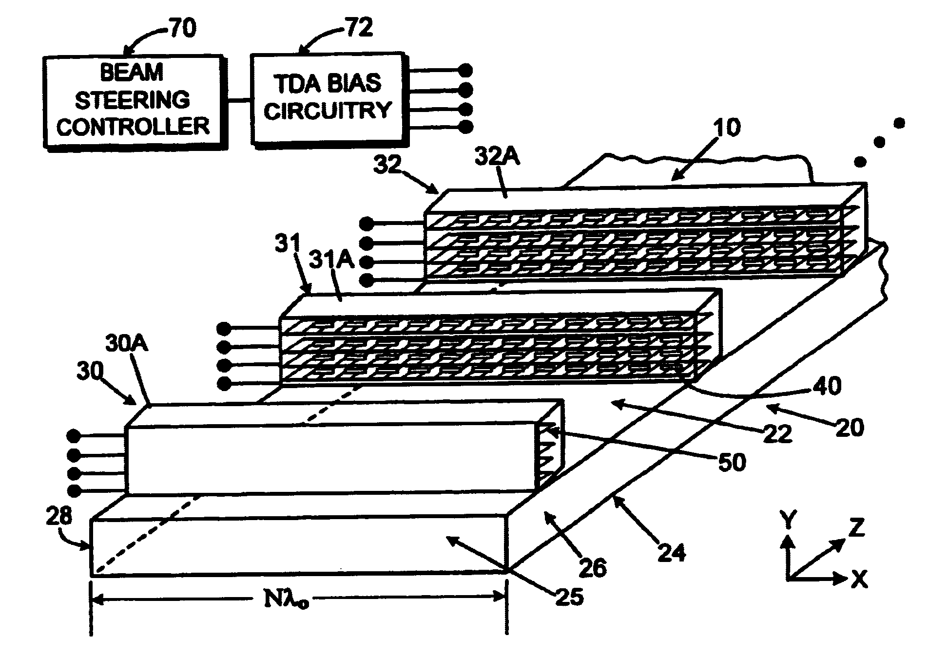
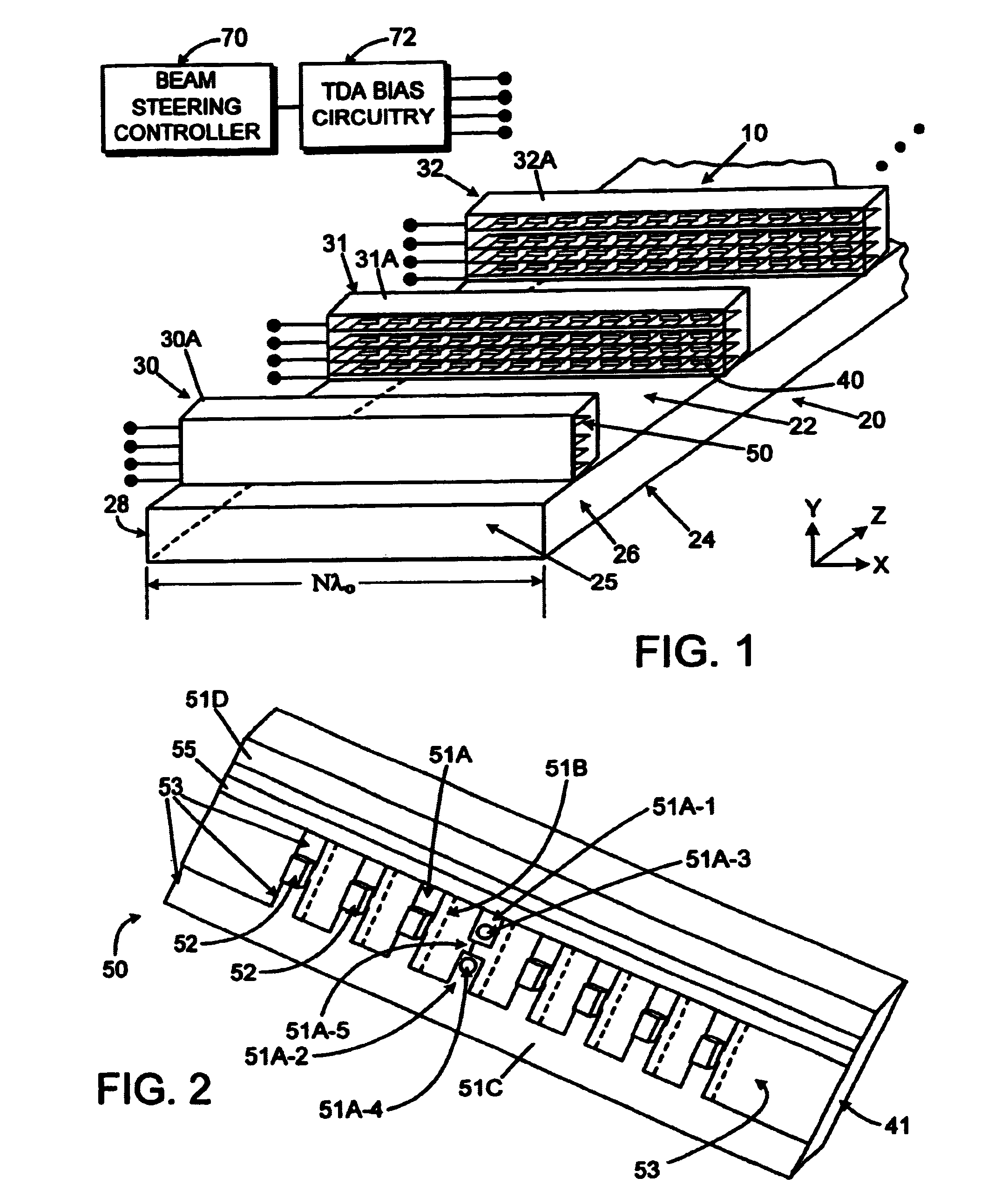
[0011]An antenna array employing continuous transverse stubs as radiating elements is described, which includes an upper conductive plate structure comprising a set of continuous transverse stubs, and a lower conductive plate structure disposed in a spaced relationship relative to the upper plate structure. The upper plate structure and the lower plate structure define an overmoded waveguide medium for propagation of electromagnetic energy. Continuous slots are cut into the top wall of the waveguide and act as waveguide couplers to couple energy in a prescribed manner into the stub radiators.

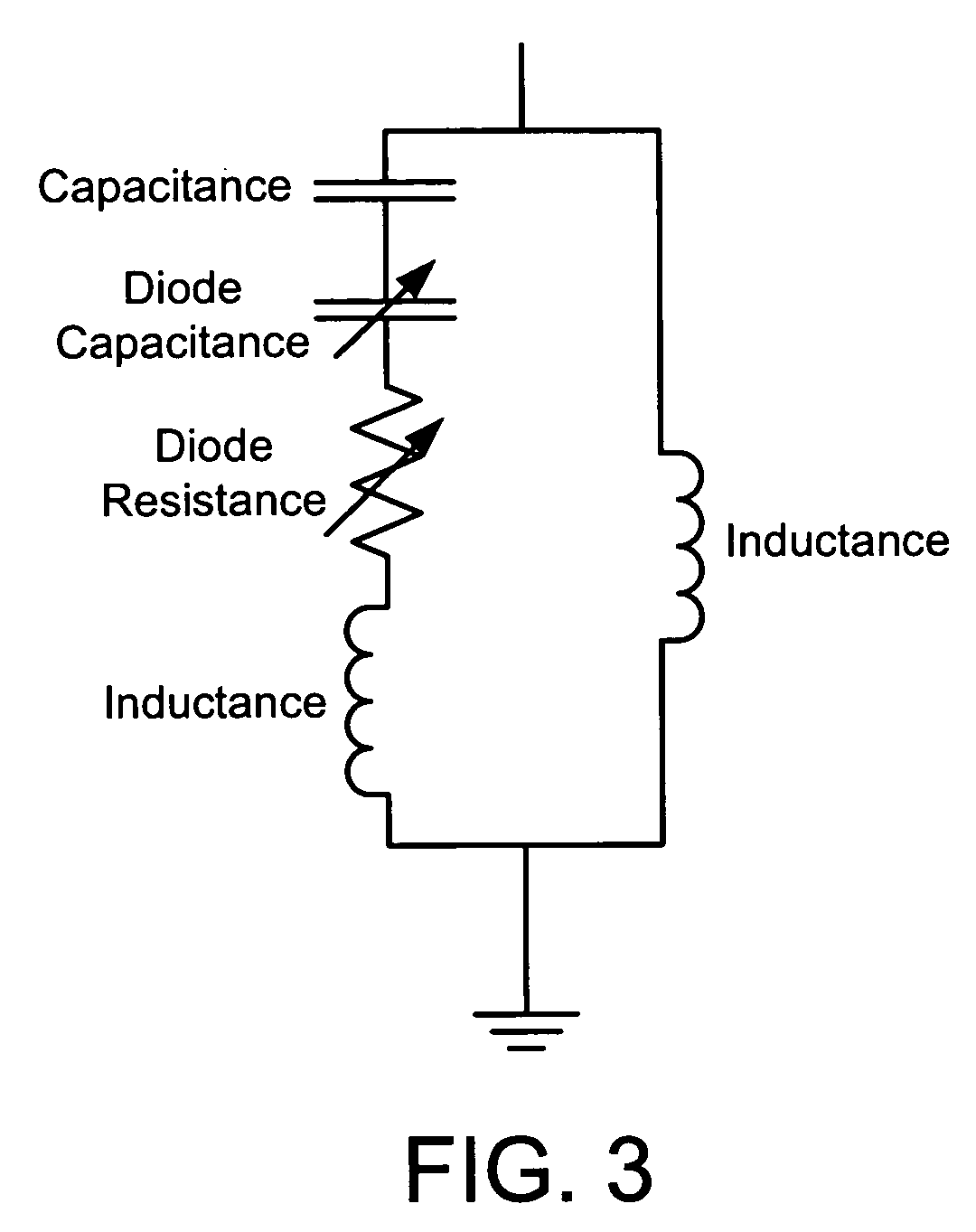
[0012]For each of the stub radiators, one or more transverse device (TDA) array phase shifters are disposed therein. Each TDA circuit comprises a generally planar dielectric substrate having a microwave circuit defined thereon, and a plurality of spaced...


PUM


Abstract

An antenna array employing continuous transverse stubs as radiating elements is described, which includes an upper conductive plate structure comprising a set of continuous transverse stubs, and a lower conductive plate structure disposed in a spaced relationship relative to the upper plate structure. The upper plate structure and the lower plate structure define an overmoded waveguide medium for propagation of electromagnetic energy. For each of the stubs, one or more transverse device array phase shifters are disposed therein.

Description

BACKGROUND OF THE DISCLOSURE[0001]It would be advantageous to provide an electronically scanned antenna (ESA) for applications that could not afford the cost and complexity of either a Transmit / Receive (T / R) module based active array or a ferrite-based phased array to achieve electronic beam scanning.[0002]Electronic scanning of a radiation beam pattern is generally achieved with Transmit / Receive (T / R) module based active arrays or ferrite-based phased arrays The former can employ a T / R module at each radiator of the ESA. The T / R module may employ monolithic microwave integrated circuits (MMICs) to provide signal amplification and a multi-bit phase shifter to scan the radiation beam pattern. The latter employs passive ferrite phase shifters at each radiator to affect beam scan. Both techniques employ expensive components, expensive and complicated feeds and are difficult to assemble. Additionally, the bias electronics and associated beam steering computer are complex. Furthermore, f...

Claims


Application Information

Patent Timeline
Patent Type & Authority Patents(United States)
IPC IPC(8): H01Q13/00H01Q19/06
CPCH01Q13/28H01Q13/20
Inventor ROBERTSON, RALSTON S.HENDERSON, WILLIAM H.LEWIS, ROBERT T.BROAS, ROMULO J.
Owner RAYTHEON CO
Why Eureka
Try Eureka