Image forming system and image forming apparatus

a technology of image forming system and forming apparatus, which is applied in the direction of digital output to print units, instruments, electrographic processes, etc., can solve the problems of ineffective power saving effect and need to wait a long time to achieve the effect of excellent power saving

Active Publication Date: 2006-09-12
MINOLTA CO LTD
View PDF14 Cites 21 Cited by
  • Summary
  • Abstract
  • Description
  • Claims
  • Application Information

AI Technical Summary

Benefits of technology

[0009]It is an object of the present invention to provide an image forming system and an image forming apparatus which are excellent in power-saving effect.

Problems solved by technology

However, even if the power-saving mode is switched to a normal operation mode by releasing the power-saving mode, the user have to wait for some time because the image output operation will start only after the temperature of the fixing roller in the fixing device has risen to a predetermined value.
However, according to the aforementioned known structure in which a human body sensor is used to detect an existence of a human body near the image forming apparatus and it is judged whether or not the power-saving mode is to be released based on the detected results by the human body sensor, there is a possibility of misjudging that a user is located near the image forming apparatus even if another person other than the user passes near the image forming apparatus, resulting in ineffective power-saving effect.
Thus, it is required to take some time until the fixing device returns to its operable temperature or the like.

Method used


Image

  • Image forming system and image forming apparatus
  • Image forming system and image forming apparatus
  • Image forming system and image forming apparatus

Examples


Embodiment Construction

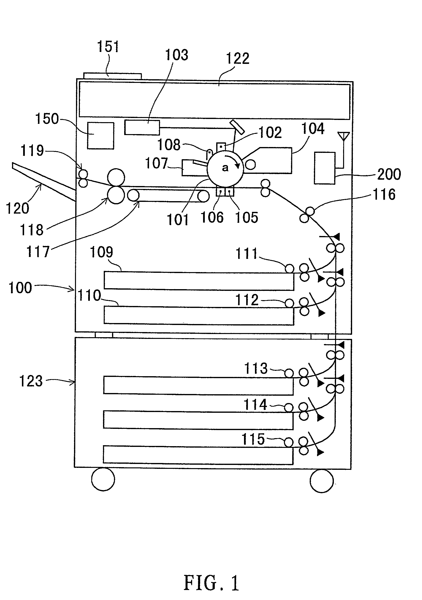
[0047]FIG. 1 is a schematic structural view showing an image forming apparatus in an image forming system according to an embodiment of the present invention.

[0048]The image forming apparatus 100 is provided with a photosensitive drum 101 rotatable in the direction of the arrow “a” at an approximately central portion thereof. Provided around the photosensitive drum 101 are an electrification device 102 for forming an image by electrophotography processing, a laser-beam scanning optical system 103, a developing device 104, a transcribing device 105, a paper detaching device 106, a cleaning device 107 for eliminating residual toner on the photosensitive drum 101, an eraser lamp 108 for removing residual charges, etc.

[0049]The detail explanation of the principle of electrophotography will be omitted since it is a well-known technology.

[0050]An electrical signal is converted into an optical signal by the laser-beam scanning optical system 103 based on the image information inputted from...


PUM


Abstract

An image forming system includes an image forming apparatus which can wirelessly transmit information that there is a waiting job and has a plurality of modes concerning power consumption, a portable terminal which can receive the information transmitted from the image forming apparatus, a position detector which detects a position of the portable terminal, and a mode switcher which switches from one mode concerning power consumption of the image forming apparatus to another in accordance with the position of the portable terminal which received the information. The position detector detects the distance between a user carrying the portable terminal and the image forming apparatus. Based on the distance data at the time when the portable terminal received the information that there is a document waiting for being outputted by the image forming apparatus, the mode concerning power consumption of the image forming apparatus is switched by the mode switcher.

Description

[0001]This application claims priority to Japanese Patent Application No. 2000-210124 filed on Jul. 11, 2000, the disclosure of which is incorporated by reference in its entirety.BACKGROUND OF THE INVENTION[0002]1. Field of the Invention[0003]The present invention relates to an image forming system and an image forming apparatus.[0004]2. Description of Related Art[0005]In image forming apparatuses such as copying machines and printers connected to a network, it is known to provide a power-saving mode for saving power at the time of waiting a job. In the power-saving mode, for example, a fixing device is kept low in temperature.[0006]However, even if the power-saving mode is switched to a normal operation mode by releasing the power-saving mode, the user have to wait for some time because the image output operation will start only after the temperature of the fixing roller in the fixing device has risen to a predetermined value.[0007]Japanese Patent Laid-open Publication No. H8-32063...

Claims


Application Information

Patent Timeline
Patent Type & Authority Patents(United States)
IPC IPC(8): G06F15/00G06F3/12
CPCG06F3/1221G06F3/1229G03G15/5004G06F3/1292G06F3/1204G06F3/1211G06F3/1285Y02B60/1271G03G15/5016G06F3/1226G03G15/5091Y02D10/00
Inventor JINBO, NORIYUKIKAMANUMA, SATOSHI
Owner MINOLTA CO LTD
Why Eureka
Try Eureka