
Illumination lamp applied at light steel frame

a technology of light steel frame and lamp body, which is applied in the direction of fixed installation, lighting and heating apparatus, lighting support devices, etc., can solve the problems of high cost, waste of materials and energy, and failure to meet power-saving requirements, so as to increase the illumination height, reduce the volume, and reduce the cost

Inactive Publication Date: 2014-03-13
HUANG CHIN CHENG
View PDF5 Cites 21 Cited by
  • Summary
  • Abstract
  • Description
  • Claims
  • Application Information

AI Technical Summary

Benefits of technology

The invention is an illumination lamp for light steel frames that has a smaller heat dissipating cover and fewer LED strips, resulting in better power saving and lower cost while maintaining the same illumination range as conventional lamps. The heat dissipating cover is designed in a trapezoid shape that allows for increased illumination height and expands the illumination range by fixing LED strips onto the cover. This results in reduced energy usage and lower costs while providing the same level of illumination.

Problems solved by technology

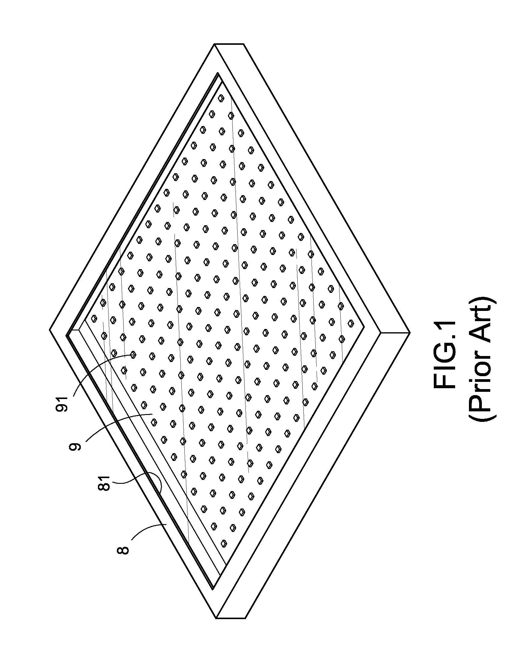
Although the aforementioned conventional illumination lamp can provide illumination, the volume of the frame 8 is too large, thus incurring a waste of materials and a high cost.
In addition, the conventional illumination lamp generally has a large number of LED elements 91 densely installed thereon to improve the brightness, but such lamp still has the drawbacks of wasting energy and failing to comply with the power-saving requirements.

Method used


Image

  • Illumination lamp applied at light steel frame
  • Illumination lamp applied at light steel frame
  • Illumination lamp applied at light steel frame

Examples


Embodiment Construction

[0013]The technical contents of the present invention will become apparent with the detailed description of preferred embodiments accompanied with the illustration of related drawings as follows.

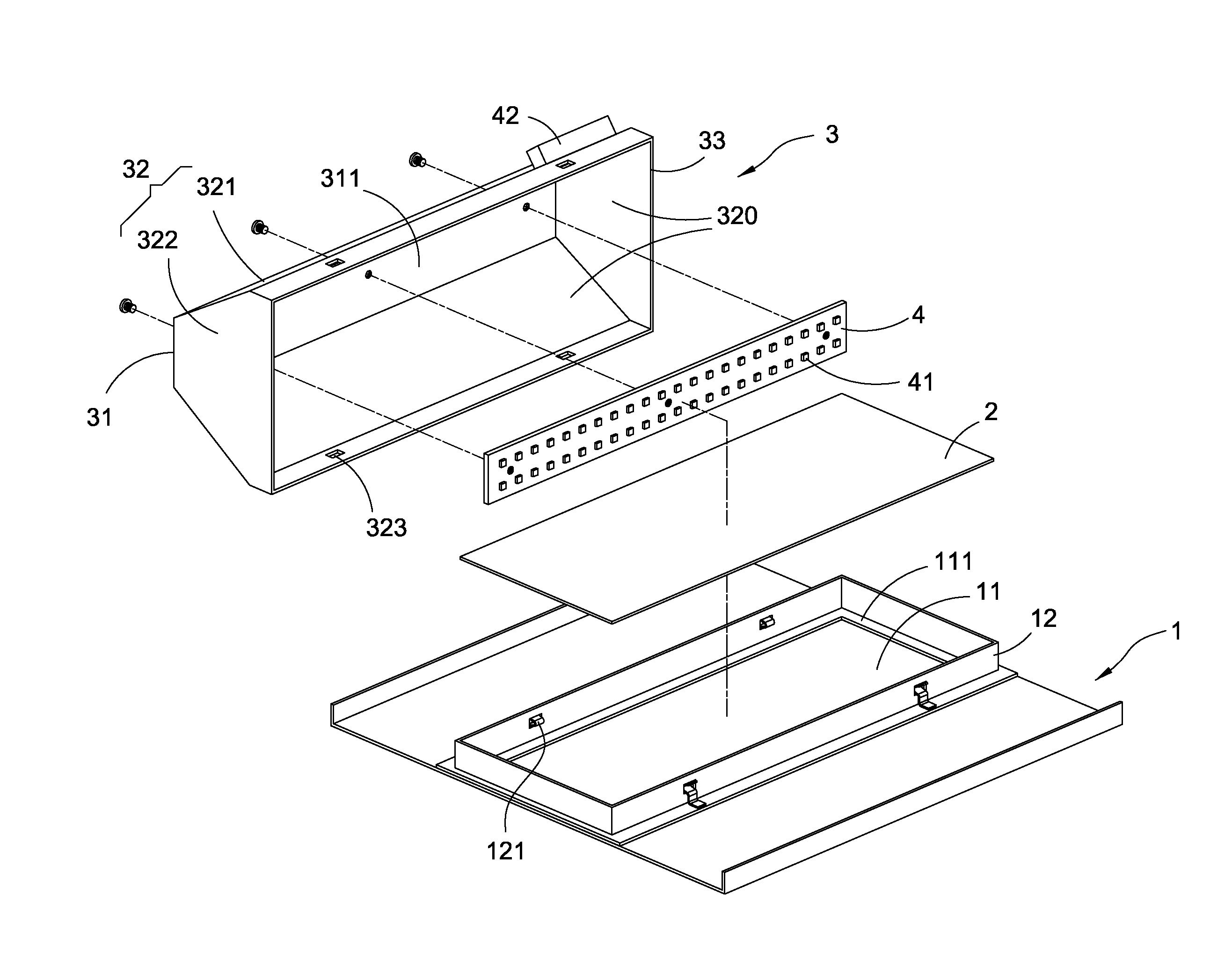
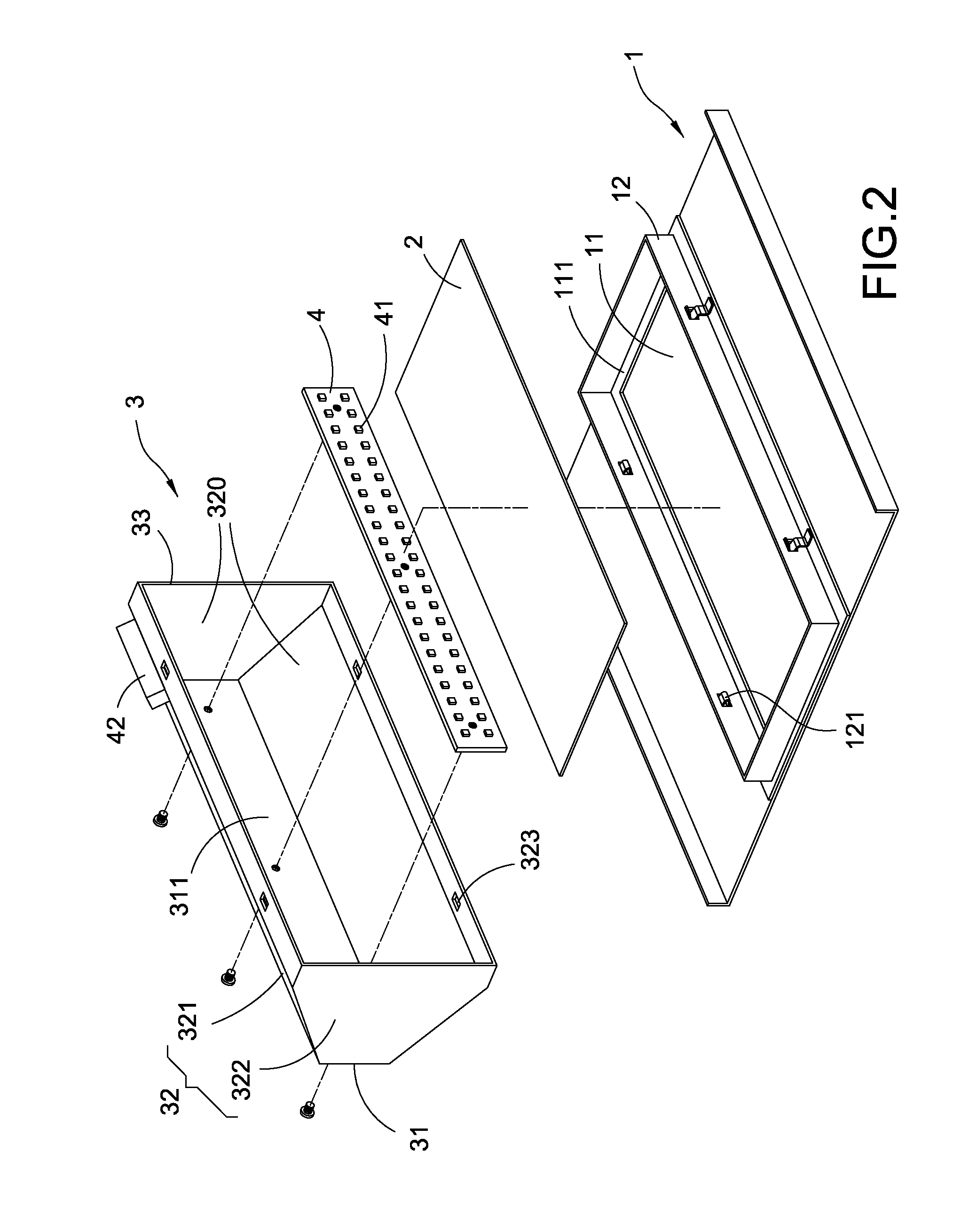
[0014]With reference to FIGS. 2 and 4 for an illumination lamp for an illumination lamp applied at a light steel frame in accordance with the present invention, an LED element 41 is used as a light emitting source and installed onto a light steel frame 5 of a ceiling, and the illumination lamp comprises a panel 1, a light exiting plate 2, a heat dissipating cover 3 and an LED strip 4.

[0015]The panel 1 is a rectangular plate with an opening 11 formed thereon, and the light exiting plate 2 is fixed to panel 1 and covered at a position corresponding to the opening 11 as shown in the figures. The panel 1 has a circular internal flange 111 protruded from the periphery of the opening 11, and the light exiting plate 2 is fixed onto an internal flange 111 of the panel 1. In addition, the light exiti...


PUM


Abstract

An illumination lamp applied at a light steel frame includes a panel, a light exiting plate, a heat dissipating cover and an LED strip. The panel has an opening; the light exiting plate is fixed to the panel and covered onto the opening; the heat dissipating cover is corresponsive to the light exiting plate and detachably installed at the panel and has a top plate and a surrounding plate coupled to the top plate, and the surrounding plate includes a pair of aslant side plate and a pair of side plates corresponding to a pair of adjacent aslant side plates, and an end of the pair of aslant side plates away from the top plate has a width greater than the width of an end proximate to the top plate; and the LED strip is flatly attached onto the internal side of the top plate.

Description

FIELD OF THE INVENTION[0001]The present invention relates to an illumination lamp, in particular to the illumination lamp applied at a light steel frame.BACKGROUND OF THE INVENTION[0002]Light emitting diode (LED) can be used as a light source and installed at a light steel frame of a ceiling. With reference to FIG. 1 for a conventional illumination lamp, the conventional illumination lamp comprises a frame 8 and a circuit board 9 having a plurality of LED elements 91 installed thereon. The frame 8 is hollow and has a downwardly opened square slot 81 and the frame 8 is a flat square body, and the circuit board 9 is substantially in a square shape and fixed on an internal top side of the frame 8, and the square open slot 81 of the frame 8 is combined with a transparent plate (not labeled with a numeral in the figure).[0003]Although the aforementioned conventional illumination lamp can provide illumination, the volume of the frame 8 is too large, thus incurring a waste of materials and...

Claims


Application Information

Patent Timeline
IPC IPC(8): F21S4/00F21V17/16F21V7/00F21V29/00F21V13/02
CPCF21S8/026F21V7/005F21V21/04F21V23/008F21V29/507F21Y2105/10F21Y2115/10
Inventor HUANG, CHIN-CHENG
Owner HUANG CHIN CHENG
Learn More