Devices and methods for detecting islanding operation of a static power source

a static power source and islanding detection technology, applied in the field of electric power, can solve the problems of compromising performance, allowing the connection of such inverters, and not desirable islanding operation, and achieve the effect of enhancing the desired performance of islanding detection and small phase angle error

Inactive Publication Date: 2006-09-12
EDA IP HLDG
View PDF13 Cites 36 Cited by
  • Summary
  • Abstract
  • Description
  • Claims
  • Application Information

AI Technical Summary

Benefits of technology

[0014]An embodiment of the present invention provides a device and method for detecting the islanding operation of an SPC, such as an inverter, connected to a grid. The device and method introduces, for example, a very small phase angle error for an output voltage of the SPC in every voltage cycle. This small phase angle error can be a positive, negative or random value. This method involves injecting a phase angle error at each of a predetermined number of control step intervals in each voltage cycle of the SPC. As an example, a very small phase angle error (e.g., 0.002°) is injected in every control step (e.g., 100 μs step). Because the injection phase angle is very small, the accumulation of the phase angle error in each voltage cycle can be controlled to be very small, in the range of less than plus or minus one degree.
[0015]The accumulated small phase angle error is corrected at each voltage cycle in synchronization with a voltage of the grid, if the grid is present. If the grid is lost, the small phase angle error existing in the SPC will not be corrected by the grid voltage, causing an initial frequency change. The initial frequency change will cause more frequency change, because the injected phase angle error exists. By properly selecting the magnitude of the small phase angle error, this initial frequency change can be controlled to have sufficient magnitude and is used to overcome the NDP or NDZ of the SPC. The initial frequency change can be accumulated, and frequency drift will occur, from cycle to cycle. The amount of initial frequency drift is used as an indication of “possible” grid loss and an “on” flag is set to enable the function block of an error frequency amplifier (EFA) with positive feedback again.
[0016]The EFA with positive feedback gain may be used to create fast frequency drift when islanding occurs to enhance the desired performance of islanding detection and protection circuit and method. The EFA is placed in “off” or “on” states depending on the existing grid condition. When the grid is present, the EFA is controlled “off”, so that the drawbacks of the method of frequency drift with positive feedback at normal operation are eliminated. When the grid is lost, the EFA is controlled “on”, so that the frequency drift speed can be accelerated. An indication of possible loss of the grid is used as the “on” signal for the EFA. For example, frequency change rate can be used as the indication of possible loss of the grid. When the frequency change rate is over a preset level, a flag will be set and “on” enabling the EFA.

Problems solved by technology

Islanding operation is not desirable due to safety concerns.
It is mandatory to have an anti-islanding feature on inverters, or utilities will not allow such inverters to be connected to the utility grid.
In addition to safety issues, islanding also has performance implications.
Current active methods of addressing the islanding problem include injecting harmonics which compromise performance.
There are also passive methods which have non-detection zones, so anti-islanding is not guaranteed for all conditions.
There is a separate issue of multi-unit operations, which also poses a problem for harmonic injection because harmonics can cancel each other.
These methods have serious drawbacks.
Such injected signals can interfere with the grid or the load.
The injected signals can also cancel each other, rendering the technique useless when two or more SPCs are connected together.
This method cannot guarantee that islanding can be detected if there are no voltage or frequency changes when islanding occurs.
However, a larger gain for positive feedback can cause the system to become unstable, while a smaller gain can potentially make the system have a larger NDZ in detecting islanding.

Method used


Image

  • Devices and methods for detecting islanding operation of a static power source
  • Devices and methods for detecting islanding operation of a static power source
  • Devices and methods for detecting islanding operation of a static power source

Examples


Embodiment Construction

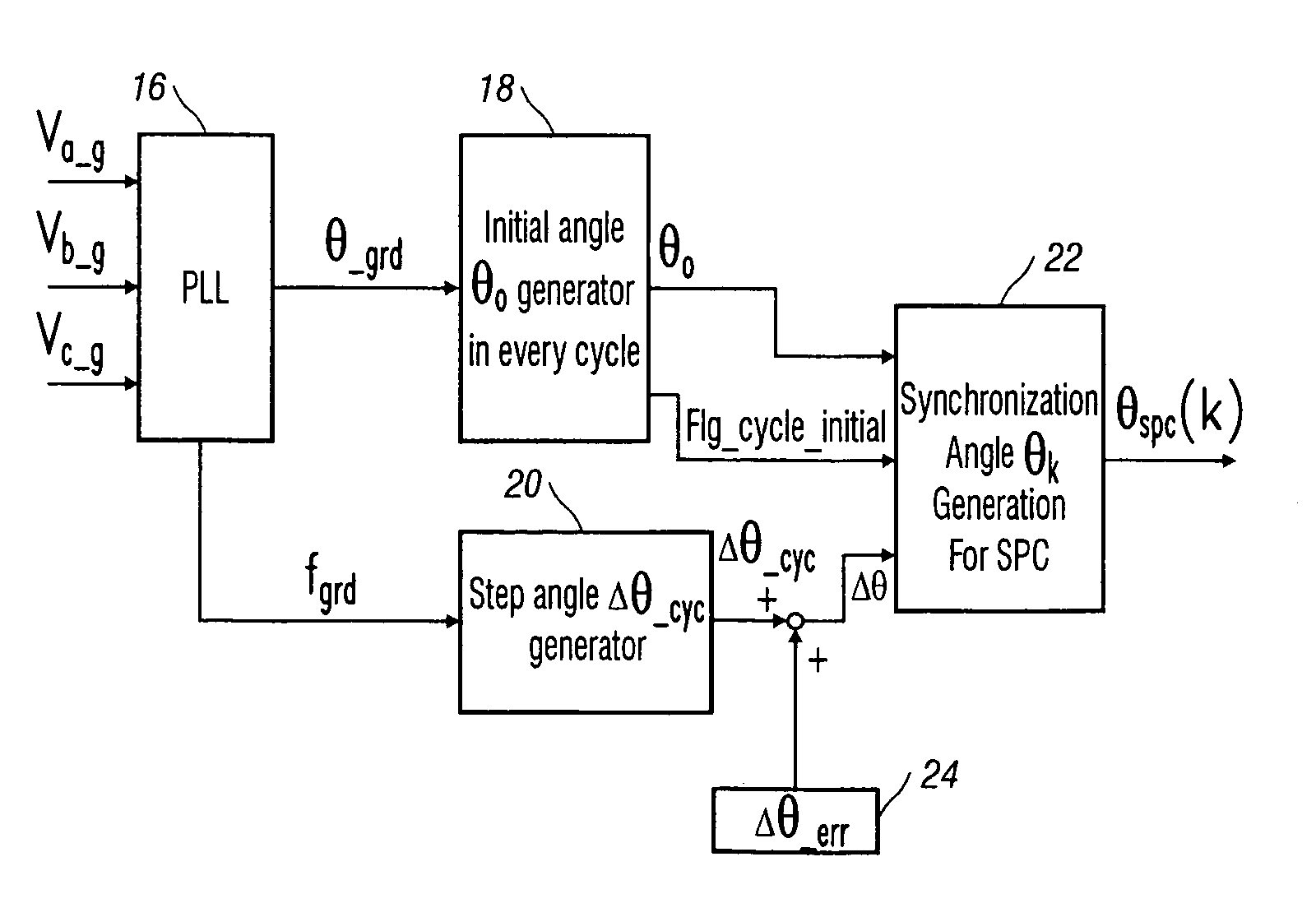
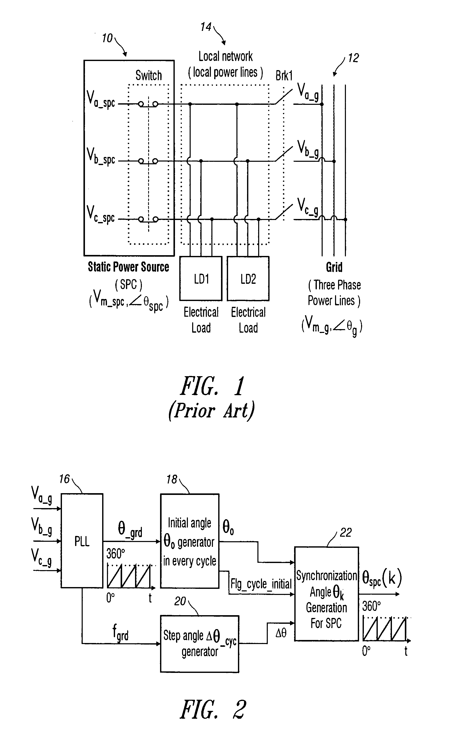
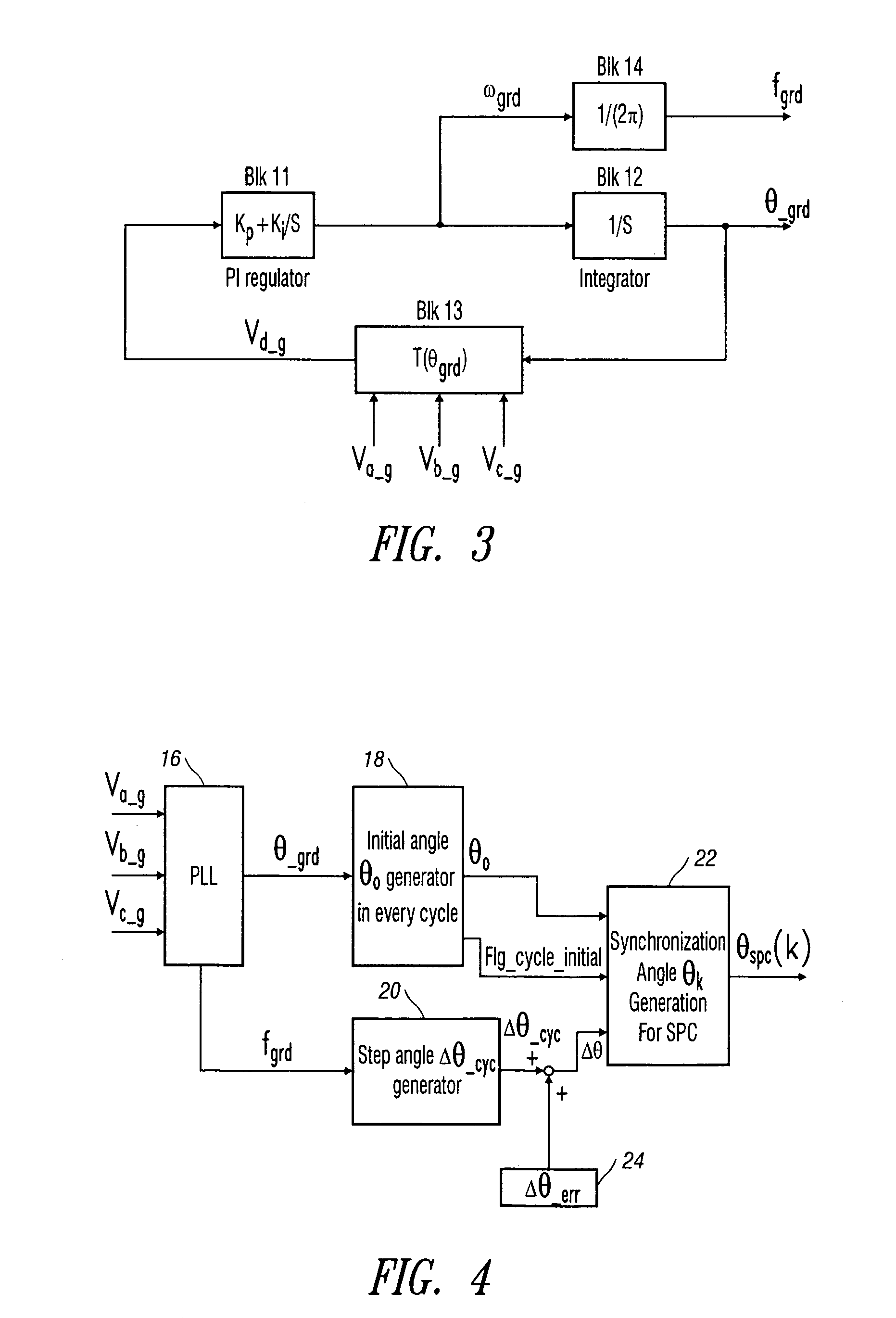
[0024]Referring now in detail to an embodiment of the present devices and methods, an example of which is illustrated in the accompanying drawings, in which like numerals designate like components, the present devices and methods provide a very reliable method of detecting islanding operation of a static power source (SPC) 10, as shown in FIG. 1, connected to a grid 12 utilizing phase angle error injection. In the normal operation of the existing grid 12, an embodiment of the present devices and methods introduces a very small phase angle error for output voltage of the SPC 10 in every voltage cycle. However, the average frequency of the SPC 10 is not influenced by the phase error, and there is no frequency drift from the output voltage of the SPC 10 because the accumulated small phase angle error is corrected at each voltage cycle in synchronization with a voltage of the grid 12, if the grid 12 is present.

[0025]In abnormal operation of a grid 12 loss, this intentional small phase e...


PUM


Abstract

Devices and methods for detecting islanding operation of a static power source involve injection of a non-harmonic error on the phase angle of the static power source in regular steps to introduce a very small intentional phase shift for the output voltage of the static power source in every voltage cycle which is corrected in each cycle in synchronization with the grid voltage in normal operation of the grid. In abnormal operation of a grid loss, this intentional small phase shift or error causes an intentional small frequency drift in each voltage cycle that continues in one cycle after another cycle. When the intentional frequency drift is over a preset level, a detection circuit starts to isolate the static power source from the grid to prevent islanding operation.

Description

BACKGROUND OF INVENTION[0001]1. Field of the Invention[0002]The present invention relates generally to the field of electric power, and more particularly to devices and methods for detecting the islanding operation of a static power source connected to a utility grid.[0003]2. Description of the Related Art[0004]FIG. 1 is a block diagram that shows an example of a static power source (SPC) 10 connected to and in parallel operation with a grid 12 when a breaker Brk 1 is closed. The electrical loads LD1 and LD2, shown hanging at local power lines 14, can obtain power from both the SPC and / or the grid when the breaker Brk 1 is closed. However, when the grid voltage Va-g, Vb-g, Vc-g is lost, for example, by opening the breaker Brk 1, the loads LD1 and LD2 can still obtain electrical power Va-spc, Vb-spc, Vc-spc from the SPC 10 through the local power lines 14. That situation, in which the operation of a local power source, such as the SPC 10 in FIG. 1, continues to power the local power ...

Claims


Application Information

Patent Timeline
Patent Type & Authority Patents(United States)
IPC IPC(8): H01H47/32H02J3/38
CPCH02J3/38H02J2003/388H02J3/388
Inventor DENG, DUOTULADHAR, ANIL
Owner EDA IP HLDG
Why Eureka
Try Eureka