
Camera and waterproof camera casing

a technology for waterproof cameras and cameras, applied in the field of cameras and waterproof camera casings, can solve the problem of meaningless housing of lens barrels, and achieve the effects of reducing the number of times of power cell exchange, enhancing portability, and reducing the consumption of cells

Active Publication Date: 2006-09-12
RICOH KK
View PDF10 Cites 78 Cited by
  • Summary
  • Abstract
  • Description
  • Claims
  • Application Information

AI Technical Summary

Benefits of technology

[0024]By so constructing the camera, even when the waterproof camera casing is attached to the camera of the present invention, the lens barrel state selector can be operated. Consequently, the waterproof camera casing can be provided, which can utilize the above-mentioned effects of the invention camera even when the waterproof camera casing is attached to the camera.
[0025]According to a still further aspect of the present invention, there is provided a waterproof camera casing configured to detachably house the camera of the present invention, which casing comprises a detector being configured to make said waterproof camera casing attachment detector of the camera detect that the camera casing is attached to the camera when the camera is housed in the camera casing.
[0026]By so constructing the camera, the waterproof camera casing attachment detector of the camera is made to automatically detect that the waterproof camera casing is attached to the camera, so that when the power supply of the camera is turned off, the lens barrel can be kept at the position in the photographing-waiting position. Thus, even when the waterproof camera casing is attached to the camera, the effects exhibited by the camera according to the present invention can be exhibited.
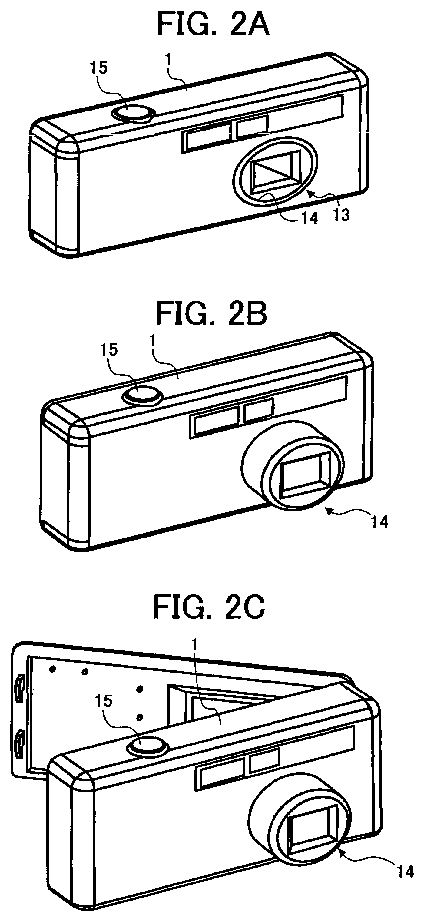
[0027]As explained above, according to the camera of the present invention in which when the barrel is in the housed state, the front face of the lens barrel is substantially in flush with the front face portion of the outer cover surrounding the front face of the lens barrel, whereas when the lens barrel is in a photographing-waiting state in which photographing is possible, the front face of the lens barrel is projected from said surrounding front face portion of the outer cover, either one of setting the lens barrel in the housed state and keeping the lens barrel at a position in the photographing-waiting state when a power supply of the camera is turned off can be selected. In addition, control is effected such that in case that the lens barrel state selector is selecting setting the lens barrel in the housed state, the lens barrel is set in the housed state when the power supply of the camera is turned off, whereas in case that the selector is selecting keeping the lens barrel at the position in the photograph-waiting state, the lens barrel is kept at the position in the photographing-waiting, when the power supply of the camera is turned off. If the selector selects the states keeping the lens barrel at the position in the photograph-waiting, the lens barrel is kept projected from the camera body and at the position in the photographing-waiting state even when the power supply of the camera is turned off. Consequently, the photographer will not miss a shutter chance, and the number of times of exchanging power cells can be decreased by reducing consumption of the cell for the camera. In addition, if the lens barrel state selector selects setting the lens barrel in the housed state, the lens barrel can be housed into the outer casing when the power supply of the camera is turned off. Thus, the present invention can provide a camera having enhanced portability.
[0028]According to the first preferred embodiment of the camera of the present invention which comprises the outer cover and a lens barrel provided such that the lens barrel is housed inside the outer cover in the state that the front face of the lens barrel is substantially flush with the front face portion of the outer cover surrounding the front face of the lens barrel, whereas when the lens barrel is in a photographing-waiting state in which photographing is possible, the front face of the lens barrel is projected from said surrounding front face portion of the outer cover, whether the waterproof camera casing is attached to the camera or not can be detected. If it is detected that a waterproof camera casing is attached to the camera, the camera is controlled such that the lens barrel is kept at the position in the photographing-waiting state when the power supply of the camera is turned off. Thus, when the camera casing is attached to the camera, the lens barrel can be automatically kept at the position in the photographing-waiting state if the power supply of the camera is turned off. Accordingly, even when the waterproof camera casing is attached to the camera, the photographer will not miss a shutter chance owing to the automatic control, and consumption of the cell for the camera can be reduced.
[0029]According to the waterproof camera casing of the present invention to which the camera according to the present invention can be detachably housed, the lens barrel state can be selected by the manipulation from the outer side of the waterproof casing. Consequently, even if the camera according to the present invention is fitted into the waterproof camera casing, the effects of the camera according to the present invention can be utilized by selecting the lens barrel state.

Problems solved by technology

When the waterproof casing is used in a rainy, sandy or dusty environment, it is meaningless to house the lens barrel into the camera body within the waterproof casing.

Method used


Image

  • Camera and waterproof camera casing
  • Camera and waterproof camera casing
  • Camera and waterproof camera casing

Examples


first embodiment

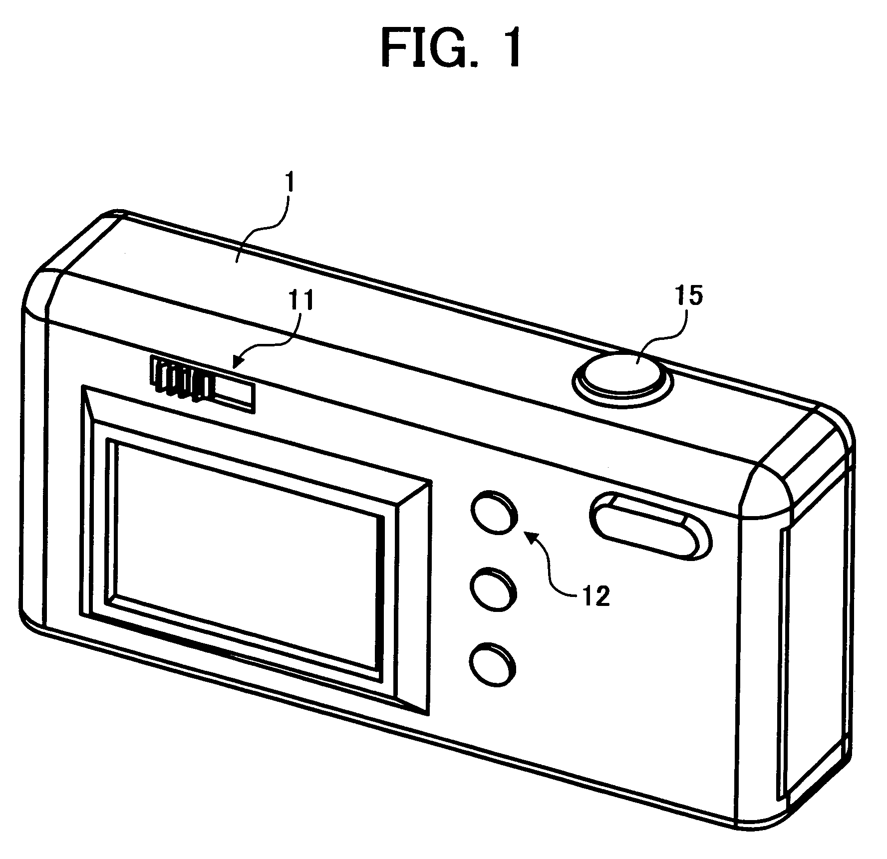
[0045]FIG. 1 is a perspective view of a front-face construction of a camera according to the first embodiment of the present invention. In FIG. 1, the camera of this embodiment comprises a camera body 1, and a lens barrel state-selecting switch 11 (a lens barrel state selector) and a power supply button 12 both arranged on the camera body. The power supply button 12 is a switch to turn on / off the power supply of the camera body 1.

[0046]In this first embodiment, the lens barrel state-selecting switch 11 is a slide-type switch. Alternatively, the switch 11 may be a toggle switch or a switch of such a type as alternatively repeating two kinds of selections every pushing, for example.

[0047]A shutter release button 15 is arranged at an upper face of the camera body 1. In first pushing down the button, operations such as photometric measurement, distance measurement and focusing are started. In a second pushing down of the button, an aperture of the shutter begins to be opened.

[0048]In th...

second embodiment

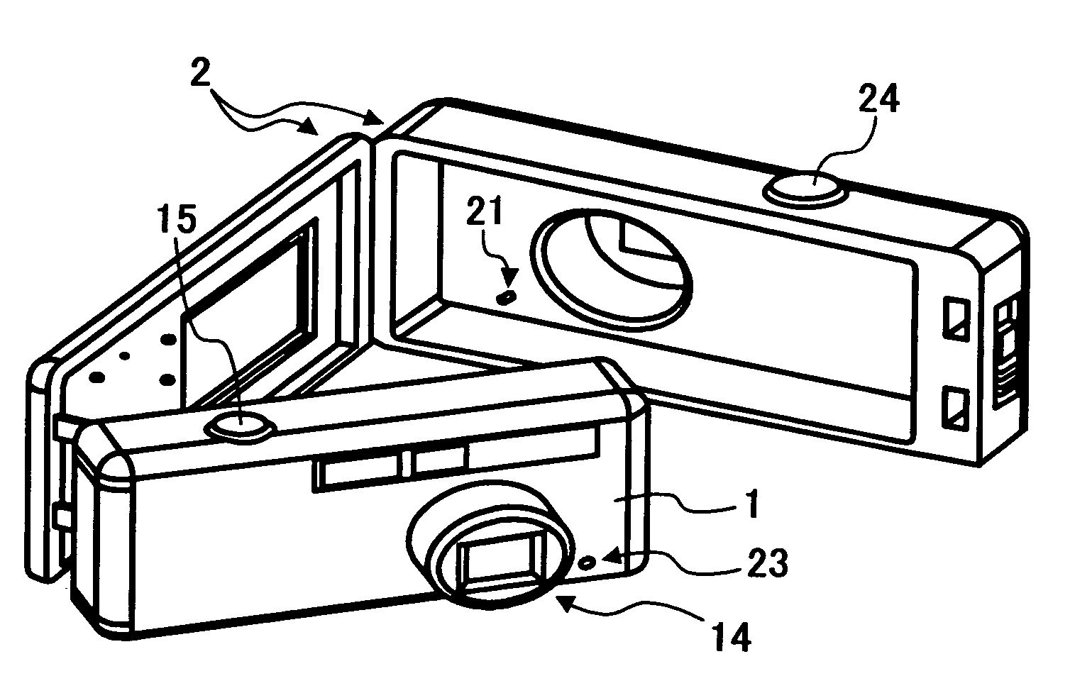
[0069]FIGS. 4, 5 and 6 are perspective views showing outer constructions of a camera and a waterproof camera casing according to a second embodiment of the present invention.

[0070]FIG. 4 is a perspective view showing a second embodiment according to the present invention, as viewed from a side of a rear face of the camera casing. In order to clarify the state that the camera is housed in the waterproof casing, FIG. 4 shows a state in which a rear lid of the camera casing is opened. FIG. 5 is a perspective view showing a front face construction of the camera and the waterproof camera casing before the camera is housed thereinto. FIG. 6 shows the outer construction of the waterproof casing in which the camera is housed.

[0071]As shown in FIGS. 4, 5 and 6, the camera of the second embodiment can be housed into the waterproof camera casing in the second embodiment.

[0072]The camera of this embodiment is the same as that of the first embodiment except that the former is additionally provid...

third embodiment

[0098]FIGS. 8, 9 and 10 are perspective views for illustrating outer constructions of a camera and a waterproof casing according to a third embodiment of the present invention.

[0099]Among these figures, FIG. 8 illustrates the camera body 1 in the state wherein a rear lid of the waterproof casing 3 is opened to show that the camera body 1 is fitted into the waterproof casing 3. FIG. 9 shows the camera body 1 and the waterproof casing 3 before the former is fitted into the latter. FIG. 10 shows the state that the camera body 1 is fitted into the waterproof casing 3.

[0100]The camera shown in FIGS. 8, 9 and 10 differs from that according to the second embodiment in that no waterproof casing detector is attached. That is, the waterproof casing attachment-detecting button 23 is not additionally provided in the camera body 1 of this third embodiment unlike the camera shown in the second embodiment. Except for this, the camera according to the third embodiment has the same construction and ...


PUM


Abstract

A camera includes an outer cover; a lens barrel which is housed inside the outer cover in the state that a front face of the lens barrel is substantially in flush with a front face portion of the outer cover surrounding the front face of the lens barrel, whereas when the lens barrel is in a photographing-waiting state in which photographing is possible, the front face of the lens barrel is projected from said surrounding front face portion of the outer cover; a lens barrel state selector for selecting either one of setting the lens barrel in the housed state and keeping the lens barrel at a position in the photographing-waiting state, when a power supply of the camera is turned off; and a controller for controlling the camera such that the lens barrel is set in the housed state when the power supply of the camera is turned off in the state that the lens barrel state selector is selecting setting the lens barrel in the housed state, whereas the lens barrel is kept at the position in the photographing-waiting state when the power supply of the camera is turned off in the state that the selector is selecting keeping the lens barrel at the position in the photograph-waiting state.

Description

BACKGROUND OF THE INVENTIONField of the Invention[0001]The present invention relates to a camera and a waterproof camera casing. Particularly, the invention relates to a compact camera which is portable while being placed in handy a bag or a pocket and which can save a power cell required for driving its lens barrel. The invention also relates to a waterproof camera casing for such a camera.[0002]As provided in conventional compact cameras, there is a so-called collapsable type camera in which a lens barrel holding a photographic lens unit therein can be housed in a camera body. When the camera is to be used to take a photograph, the lens barrel is projected (extended) from the camera body and the projected state is maintained. When the camera is to be carried after the photographing, the lens barrel is housed in the camera body again for improving convenience.[0003]In case of such a conventional camera, a main trend in such a system is that the lens barrel is automatically projecte...

Claims


Application Information

Patent Timeline
Patent Type & Authority Patents(United States)
IPC IPC(8): G03B17/08G03B17/04G03B17/02H04N5/225H04N5/232
CPCH04N5/232H04N5/2252H04N23/50H04N23/51H04N23/651
Inventor SATO, ATSUSHI
Owner RICOH KK
Learn More