Wood splitter with multiple wood splitting wedges on a rotating member

a wood splitter and rotating member technology, applied in the field of wood splitter with multiple wood wedges on a rotating member, can solve the problems of increasing the cost of log splitting operation, too small pieces, manual splitting of wood, etc., and achieves the effect of quick and easy rotation, low cost, and easy rotation

Inactive Publication Date: 2006-09-19
ALBRIGHT DAVID B
View PDF8 Cites 9 Cited by
  • Summary
  • Abstract
  • Description
  • Claims
  • Application Information

AI Technical Summary

Benefits of technology

[0010]The rotational member can be rotated in a generally circular path about a longitudinal axis of the machine so that each of the splitting wedges carried on the rotational member can be selectively positioned for splitting logs placed in the log cradle or bed. An operator can then quickly and easily switch from one size splitting wedge to another size splitting wedge by simply rotating the rotational member in order to place the appropriate wedge into the action position behind the log cradle or bed. At the same time, the bed or cradle guiding the log to be split can be adjusted vertically to properly center the log at the center of the selected wedge.
[0011]The rotational member with its splitting wedges radially attached thereon is preferably removable from the rear end of the wood splitter frame so that different sets of splitting wedges could be used on the same wood splitting machine. For example, using two rotational members supporting three splitting wedge sizes, one set of wedges could be mounted on one rotational member for splitting various sizes of smaller logs, and a different set of wedges could be mounted on the other rotational member for splitting different size larger logs. This removable feature provides greater flexibility for the wood splitting machine of the present invention to operate over a large range of log sizes.
[0014]In another embodiment of the present invention, the splitting wedges are each removably attached to the rotational member by use of fasteners or the like. The use of removable wedges allows the machine to be equipped with a multitude of splitting wedges over a large range of sizes, without having to remove the rotational member, simply by replacing the wedges.
[0016]It is therefore an object of the present invention to provide a wood splitting machine which has a plurality of splitting wedges of various sizes mounted on a rotational member such that an operator can quickly and easily rotate the appropriate splitting wedge into position depending on the diameter of the log to be split.
[0018]A further object of the present invention is to provide a wood splitting machine in accordance with the preceding objects in which at least two, and preferably three, different splitting wedges are equally spaced around the rotational member such that the wedges extend outwardly from the rotational member in a generally radial direction and an operator can quickly and easily rotate the appropriate wedge into position depending on the diameter of the log to be split.
[0022]Yet another object of this invention to be specifically enumerated herein is to provide a wood splitter in accordance with the preceding objects and which will conform to conventional forms of manufacture, be of simple construction and easy to use so as to provide a machine that will be economically feasible, long lasting and relatively trouble free in operation.

Problems solved by technology

Pieces too large in size result in customers having to manually split their wood further, whereas pieces that are too small in size cannot be used efficiently.
Such adjustment of the apparatus to accommodate varying sized logs requires considerable operator time and down time of the machine, thereby increasing the cost of the log splitting operation.
Such changeover of the different wedges, however, causes the operator to cease production temporarily with resultant lost operator time and machine down time.
This type of equipment, however, frequently results in increased small waste pieces.

Method used


Image

  • Wood splitter with multiple wood splitting wedges on a rotating member
  • Wood splitter with multiple wood splitting wedges on a rotating member
  • Wood splitter with multiple wood splitting wedges on a rotating member

Examples


Embodiment Construction

[0034]Although preferred embodiments of the invention are explained in detail, it is to be understood that other embodiments are possible. Accordingly, it is not intended that the invention is to be limited in its scope to the details of constructions and arrangement of components set forth in the following description or illustrated in the drawings. The invention is capable of other embodiments and of being practiced or carried out in various ways. Also, in describing the preferred embodiments, specific terminology will be resorted to for the sake of clarity. It is to be understood that each specific term includes all technical equivalents which operate in a similar manner to accomplish a similar purpose.

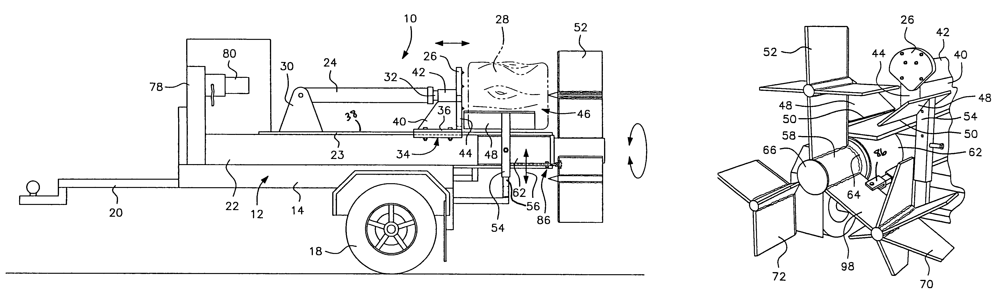
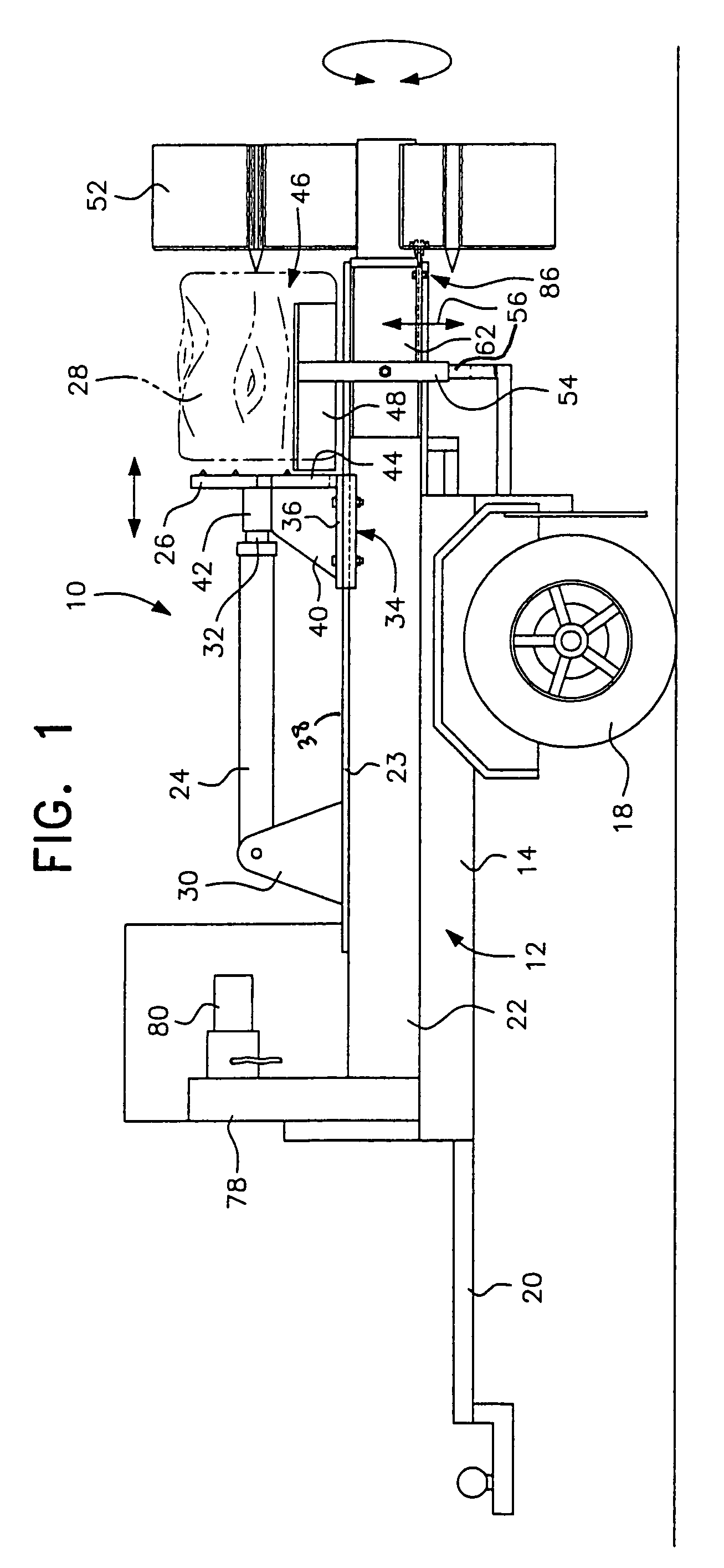
[0035]Referring to FIG. 1, a wood splitter with multiple wood splitting wedges on a rotating member in connection with the present invention is generally designated by reference numeral 10. The wood splitting machine 10 includes a chassis or frame generally designated by reference ...


PUM


Abstract

A woodsplitting machine has a plurality of wedges of various sizes and configurations radially attached to a rotational member mounted on the frame behind the log cradle such that an operator can quickly and easily rotate the appropriate wedge into position depending on the diameter of the log in the cradle to be split. The rotational member can be hydraulically actuated such that the wedges can be rotated around the longitudinal axis of the machine with little effort for the operator. An alternate embodiment provides that the rotational member be manually rotated such that the wedges can be rotated around the longitudinal axis of the machine by the hand of the operator.

Description

BACKGROUND OF INVENTION[0001]1. Field of Invention[0002]The present invention relates to a machine or apparatus for splitting wooden logs into small pieces useful as firewood. More specifically, the present invention relates to a vehicle mounted wood splitter operated by hydraulic pressure to force the cut wood logs through a splitting wedge which splits the cut log into a desired number of pieces.[0003]2. Description of Related Art[0004]The vast majority of woodsplitters to which the present invention is directed generally employ a ram-type mechanism which forces a “blocked” piece of wood of some maximal length into a stationary splitting wedge having sharpened edges. As the blocked piece or cut log is axially advanced into the wedge, the log is split into a plurality of sector-shaped pieces along cleavage lines that are generally directed radially with respect to the center axis and along medullar rays of the cut log. Typical examples of such devices are disclosed in U.S. Pat. Nos...

Claims


Application Information

Patent Timeline
Patent Type & Authority Patents(United States)
IPC IPC(8): B27L7/02B27L7/06B27L7/00
CPCB27L7/06
Inventor ALBRIGHT, DAVID B.
Owner ALBRIGHT DAVID B
Why Eureka
Try Eureka