Connector for a switch module

Inactive Publication Date: 2014-12-04
ARCADYAN
View PDF2 Cites 0 Cited by
  • Summary
  • Abstract
  • Description
  • Claims
  • Application Information

AI Technical Summary

Benefits of technology

[0007]In accordance with an aspect of the present invention, a connector is provided, which uses a s

Problems solved by technology

The built-in antenna is limited to the restricted disposition space and the circuit interference so that the effect of receiving and sending signals is poor.
However, the conventional connectors

Method used


Image

  • Connector for a switch module
  • Connector for a switch module
  • Connector for a switch module

Examples


Example

[0020]The present invention will now be described more specifically with reference to the following embodiments. It is to be noted that the following descriptions of preferred embodiments of this invention are presented herein for the purposes of illustration and description only; it is not intended to be exhaustive or to be limited to the precise form disclosed.

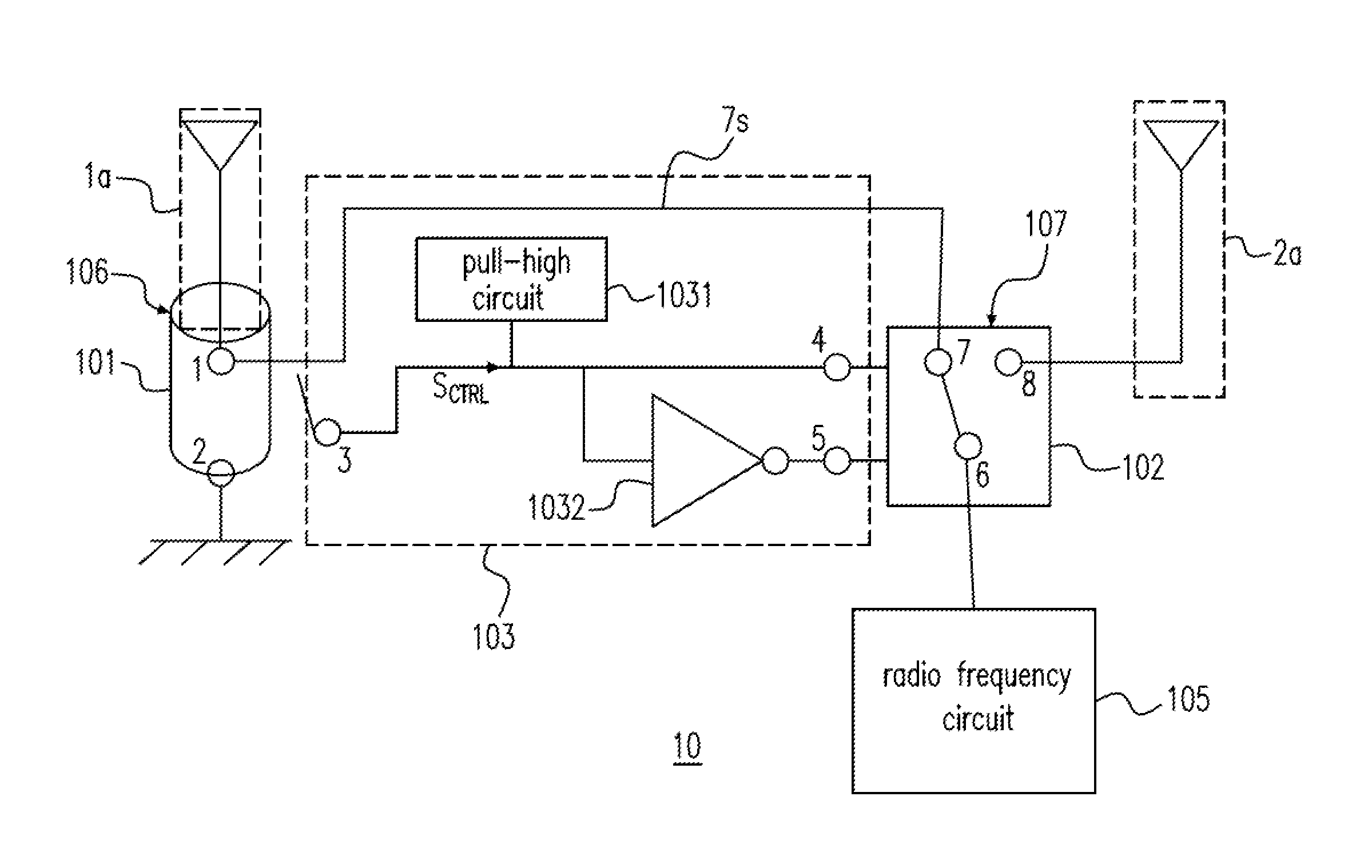
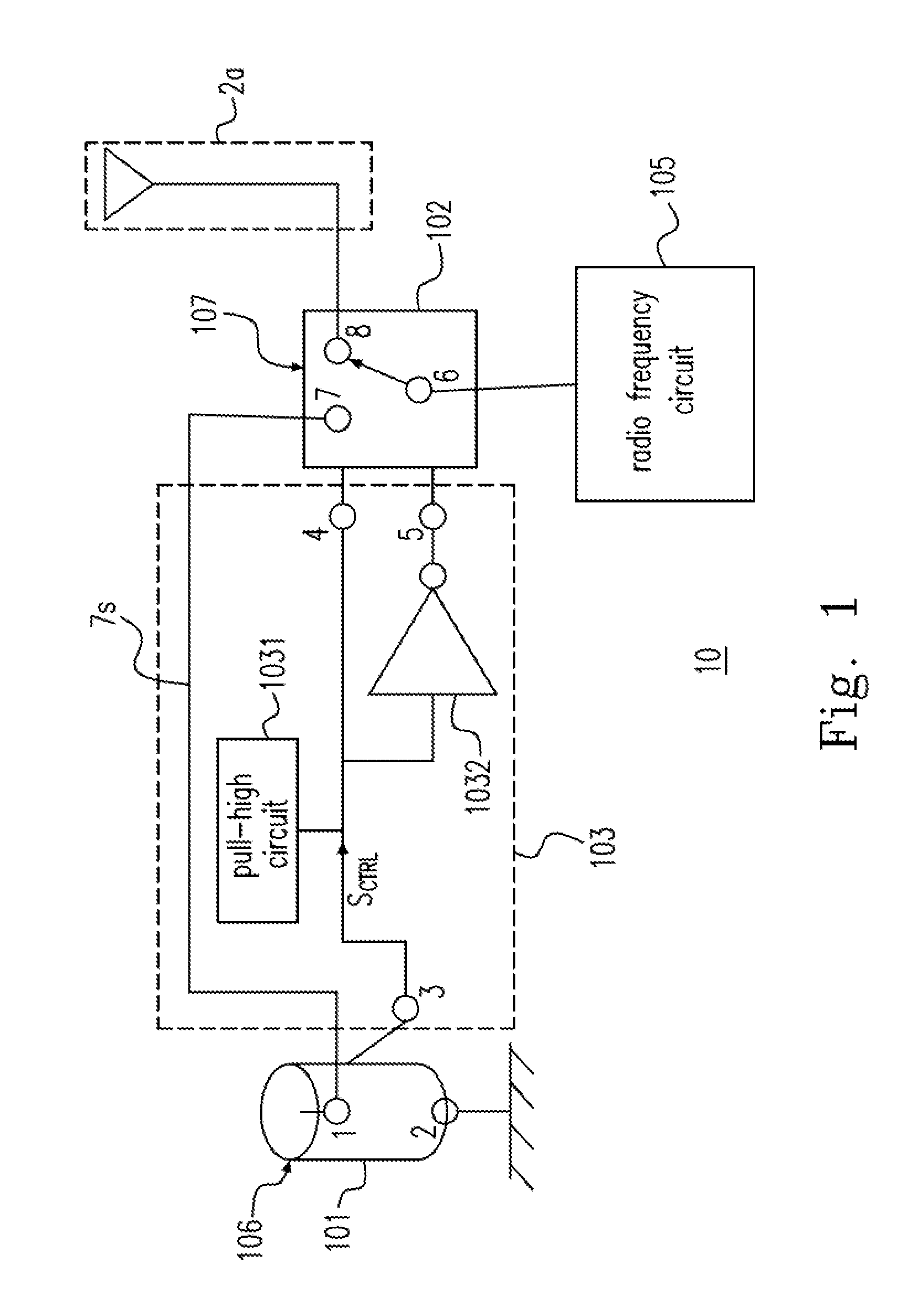
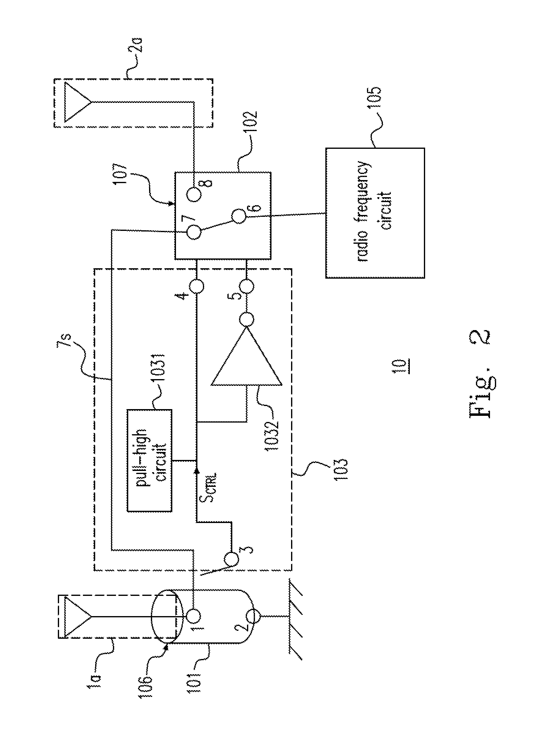
[0021]Please refer to FIG. 1, which shows a wireless transmit receive unit 10 according to an embodiment of the present invention. The wireless transmit receive device 10 includes a connector 101, a signal switch 102 and a control circuit 103. The wireless transmit receive device 10 further includes a built-in antenna 2a and a radio frequency circuit 105. Preferably, the connector 101 can be a mechanical switch 106 for being connected to an external antenna (not shown). Preferably, the signal switch 102 can be an electronic switch 107.

[0022]The connector 101 has contacts 1 and 2. The contact 1 is connected to the contact 7 o...


PUM


Abstract

A connector is provided. The connector includes a first cavity, including a housing conductor having a receiving space formed at an inner side thereof, and connected to a ground; and a signal conductor disposed in the receiving space; a second cavity fixed to a side of the first cavity; and a flexible conductor having a connecting end, a propping end and an arc structure, wherein the connecting end is electrically connected to a control circuit, the propping end props the housing conductor, the arc structure is disposed in the second cavity and has a specific shape and a flexibility, and when the signal conductor is connected to a joint of a first antenna, the specific shape is deformed to cause the propping end to be disconnected from the housing conductor, thereby causing the control circuit to enable the first antenna.

Description

CROSS-REFERENCE TO RELATED APPLICATION AND CLAIM OF PRIORITY[0001]The application claims the benefit of Taiwan Patent Application No. 102119016, filed on May 29, 2013, in the Taiwan Intellectual Property Office, the disclosures of which are incorporated herein in their entirety by reference.FIELD OF THE INVENTION[0002]The present invention relates to a switch module, and more particularly to a switch module for a connector.BACKGROUND OF THE INVENTION[0003]Many wireless communication devices are equipped with a built-in antenna disposed near the main circuit of the wireless communication device. The built-in antenna is limited to the restricted disposition space and the circuit interference so that the effect of receiving and sending signals is poor. Therefore, some wireless communication devices reserve a connecting terminal for the external antenna so that the above issues can be improved by the external antenna.[0004]When the external antenna is not connected to the wireless commu...

Claims


Application Information

Patent Timeline
IPC IPC(8): H01Q21/00H01R33/96
CPCH01R33/96H01Q21/0006H01R24/46H01R29/00
Inventor YEH, CHUN-HUNGLIN, HAO-FEI
Owner ARCADYAN
Why Eureka
Try Eureka