Connector for a switch module

a technology of switch module and connector, which is applied in the direction of electrical discharge lamps, particular array feeding systems, coupling device connections, etc., can solve the problems of poor reception and sending signals, enhanced production costs, and complex manufacturing processes of these devices, and achieves the effect of simple structure and quick and easy switching of signals of different antennas

Inactive Publication Date: 2016-10-18
ARCADYAN
View PDF4 Cites 1 Cited by
  • Summary
  • Abstract
  • Description
  • Claims
  • Application Information

AI Technical Summary

Benefits of technology

[0007]In accordance with an aspect of the present invention, a connector is provided, which uses a simple structure and a control circuit to quickly and easily switch the signals of different antennas.
[0008]In accordance with another aspect of the present invention, a connector is provided. The connector includes a first cavity, including a housing conductor having a receiving space formed at an inner side thereof, and connected to a ground; and a signal conductor disposed in the receiving space; a second cavity fixed to a side of the first cavity; and a flexible conductor having a connecting end, a propping end and an arc structure, wherein the connecting end is electrically connected to a control circuit, the propping end props the housing conductor, the arc structure is disposed in the second cavity and has a specific shape and a flexibility, and when the signal conductor is connected to a joint of a first antenna, the specific shape is deformed to cause the propping end to be disconnected from the housing conductor, thereby causing the control circuit to enable the first antenna.

Problems solved by technology

The built-in antenna is limited to the restricted disposition space and the circuit interference so that the effect of receiving and sending signals is poor.
However, the conventional connectors having the signal switch function need to be implemented by extremely complicated mechanisms so that the manufacturing processes thereof are complex and the production costs thereof are enhanced.

Method used


Image

  • Connector for a switch module
  • Connector for a switch module
  • Connector for a switch module

Examples


embodiment 1

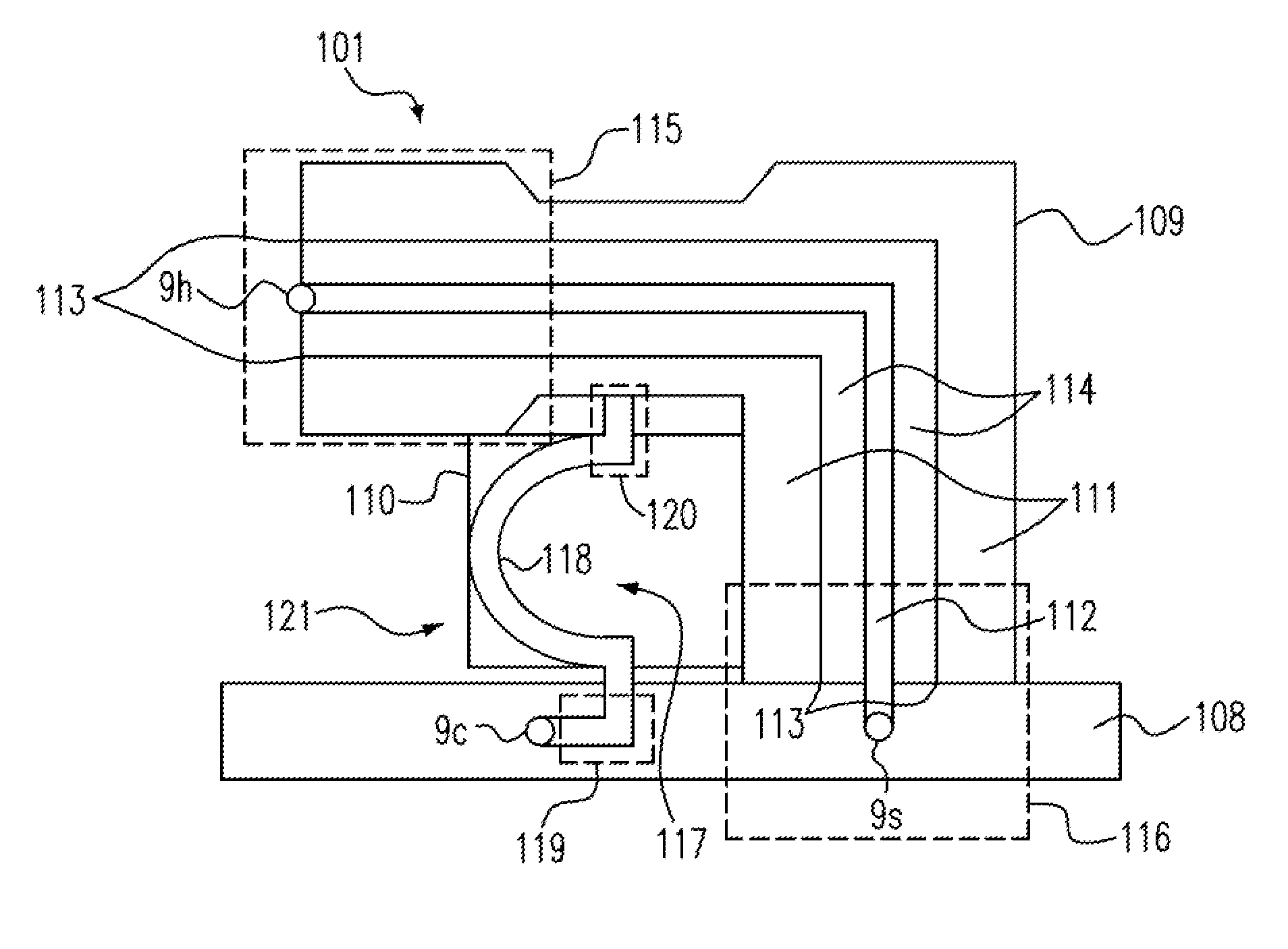
[0058]a flexible conductor having a connecting end, a propping end and an arc structure, wherein the connecting end is electrically connected to a control circuit, the propping end props the housing conductor, the arc structure is disposed in the second cavity and has a specific shape and a flexibility, and when the signal conductor is connected to a joint of a first antenna, the specific shape is deformed to cause the propping end to be disconnected from the housing conductor, thereby causing the control circuit to enable the first antenna.[0059]2. The connector of Embodiment 1, wherein:

[0060]the first cavity further includes a first insulator disposed in the receiving space and separating the signal conductor from the housing conductor; and

[0061]the second cavity further includes a second insulator covering a portion of the flexible conductor that contacts the joint of the first antenna and separating the flexible conductor from the housing conductor.[0062]3. The connector of any ...

embodiment 14

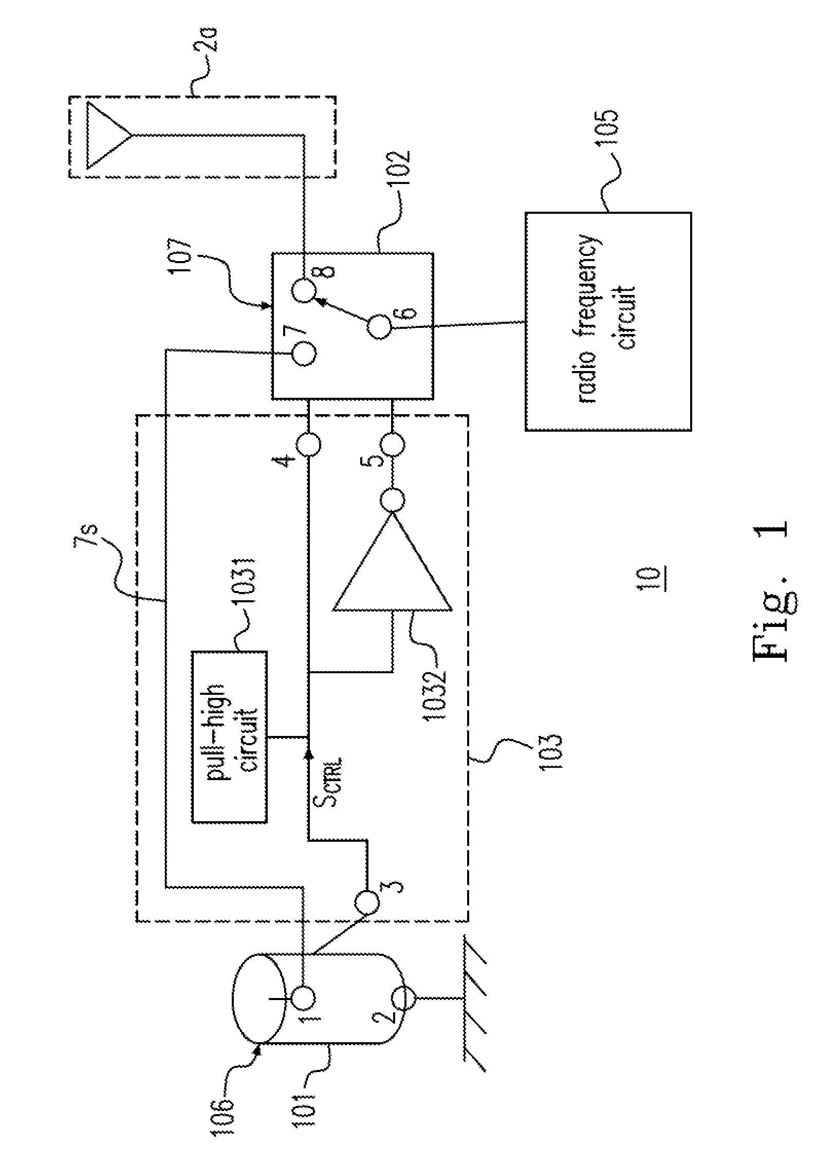
[0103]a control circuit electrically connected to the switch device, causing the first terminal to be connected to one of the first antenna terminal and the second terminal when the third terminal is connected to the fourth terminal, and causing the first terminal to be connected to the other of the first antenna terminal and the second terminal when the third terminal is disconnected from the fourth terminal.[0104]15. The switch module of Embodiment 14, wherein:

[0105]the second antenna terminal is coupled to the second terminal via the control circuit;

[0106]the switch device includes a signal switch and a connector, and the connector includes a housing conductor;

[0107]the signal switch has the first antenna terminal, the first terminal and the second terminal;

[0108]the connector has the second antenna terminal and the fourth terminal; and

[0109]the control circuit further includes a pull-high circuit and an inverter, the pull-high circuit is electrically connected to the signal swit...

embodiment 17

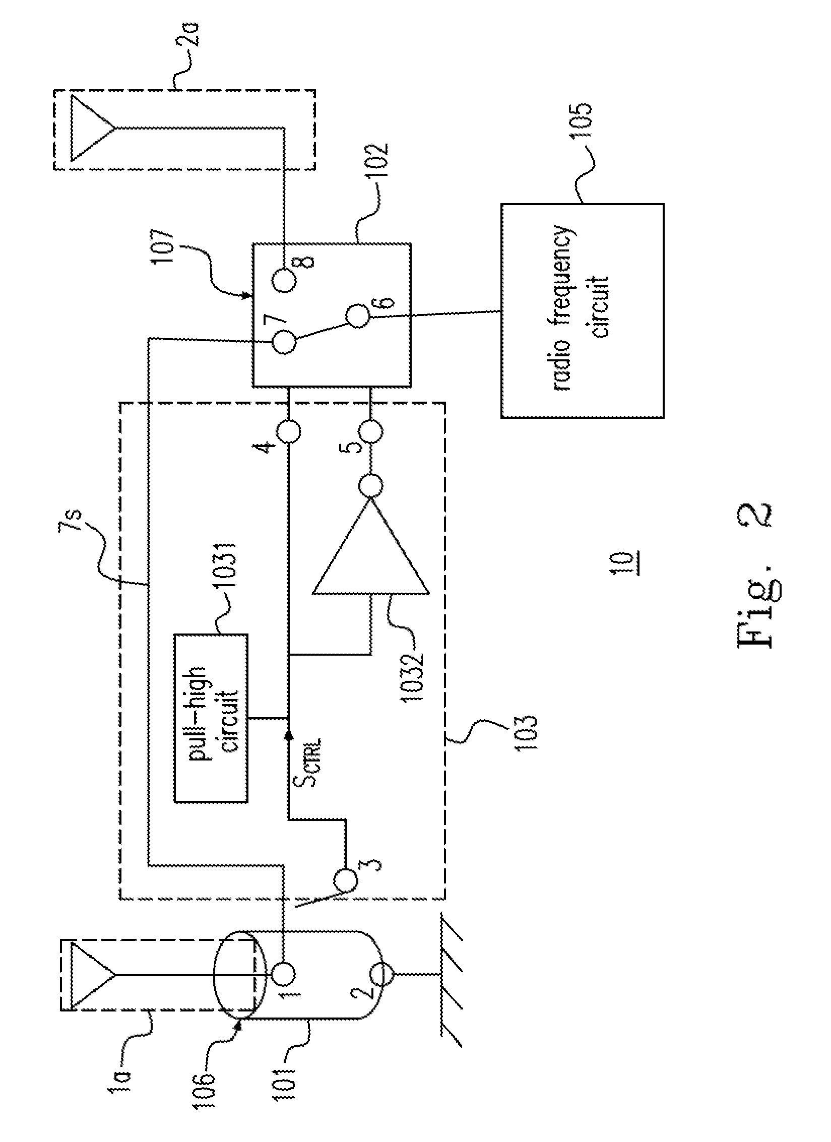
[0117]a flexible conductor having a first conductor terminal electrically connected to the third terminal, and a second conductor terminal, wherein when the second conductor terminal is connected to the fourth terminal, the switch module causes the first terminal to be connected to one of the first antenna terminal and the second terminal, and when the second conductor terminal is disconnected from the fourth terminal, the switch module causes the first terminal to be connected to the other of the first antenna terminal and the second terminal.[0118]18. The connector of Embodiment 17, wherein:

[0119]the switch module is connected to the second antenna terminal of the connector via the second terminal;

[0120]the switch module is connected to a radio frequency circuit via the first terminal; and

[0121]the connector is connected to an external antenna via the second antenna terminal.[0122]19. The connector of any one of Embodiments 17-18, wherein:

[0123]when the external antenna is connect...


PUM


Abstract

A connector is provided. The connector includes a first cavity, including a housing conductor having a receiving space formed at an inner side thereof, and connected to a ground; and a signal conductor disposed in the receiving space; a second cavity fixed to a side of the first cavity; and a flexible conductor having a connecting end, a propping end and an arc structure, wherein the connecting end is electrically connected to a control circuit, the propping end props the housing conductor, the arc structure is disposed in the second cavity and has a specific shape and a flexibility, and when the signal conductor is connected to a joint of a first antenna, the specific shape is deformed to cause the propping end to be disconnected from the housing conductor, thereby causing the control circuit to enable the first antenna.

Description

CROSS-REFERENCE TO RELATED APPLICATION AND CLAIM OF PRIORITY[0001]The application claims the benefit of Taiwan Patent Application No. 102119016, filed on May 29, 2013, in the Taiwan Intellectual Property Office, the disclosures of which are incorporated herein in their entirety by reference.FIELD OF THE INVENTION[0002]The present invention relates to a switch module, and more particularly to a switch module for a connector.BACKGROUND OF THE INVENTION[0003]Many wireless communication devices are equipped with a built-in antenna disposed near the main circuit of the wireless communication device. The built-in antenna is limited to the restricted disposition space and the circuit interference so that the effect of receiving and sending signals is poor. Therefore, some wireless communication devices reserve a connecting terminal for the external antenna so that the above issues can be improved by the external antenna.[0004]When the external antenna is not connected to the wireless commu...

Claims


Application Information

Patent Timeline
Patent Type & Authority Patents(United States)
IPC IPC(8): H01Q21/00H01R33/96H01R24/46H01R29/00
CPCH01Q21/0006H01R24/46H01R29/00H01R33/96
Inventor YEH, CHUN-HUNGLIN, HAO-FEI
Owner ARCADYAN
Why Eureka
Try Eureka