Vacuum pump valve

a vacuum pump and valve body technology, applied in mechanical equipment, functional valve types, transportation and packaging, etc., can solve the problems of deteriorating food contained in containers, increasing the manufacturing cost of sealing valves as well as the respective containers as a whole, and significant air trapped at the boundary, so as to achieve the effect of sealing a particular container

Inactive Publication Date: 2006-09-19
INTELLI INNOVATIONS
View PDF7 Cites 18 Cited by
  • Summary
  • Abstract
  • Description
  • Claims
  • Application Information

AI Technical Summary

Benefits of technology

[0009]A main object of the present invention is to provide a vacuum pump valve which is capable of effectively sealing a particular container in a vacuum manner, so as to retain a vacuum environment within the container for a prolonged period of time.
[0011]Another object of the present invention is to provide a vacuum pump valve which is adapted for use in plastic bags as well as rigid containers so as to maximize its range of applications. In other words, the present invention is suitable for use in a wide variety of containers.
[0013]Another object of the present invention is to provide a vacuum pump valve which is easy and convenient to use, and economical to manufacture, so as to minimize the ultimate selling price of the present invention for widespread application thereof.

Problems solved by technology

As a result, if there was substantial re-entering of air, the container would be filled with considerable amount of air which eventually contaminates micro-organisms and bacteria within the container sufficient to deteriorate the food contained in the container.
Conventional vacuum valve for sealing this vacuum opening is generally unsatisfactory in that leakage frequently occurs between the container and its exterior so that air can pass through the vacuum opening and deteriorates the food in the container, which is originally supposed to be preserved for a prolonged period of time.
For example, a sealing valve for sealing a plastic bag may not be suitable to employ in a rigid container so that another different kind of sealing valve is needed.
This inevitably increases the manufacturing cost of the sealing valve as well as the respective container as a whole.
For example, when a plastic bag is being vacuumed and collapsing, a boundary between the sealing valve and the plastic bag may not be fittedly aligned so that a significant amount of air is trapped at the boundary.

Method used


Image

  • Vacuum pump valve
  • Vacuum pump valve
  • Vacuum pump valve

Examples


Embodiment Construction

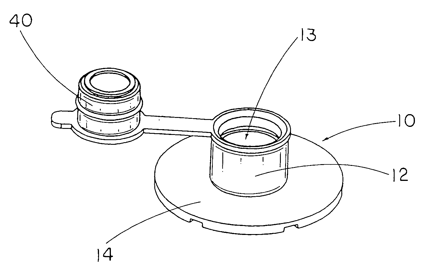
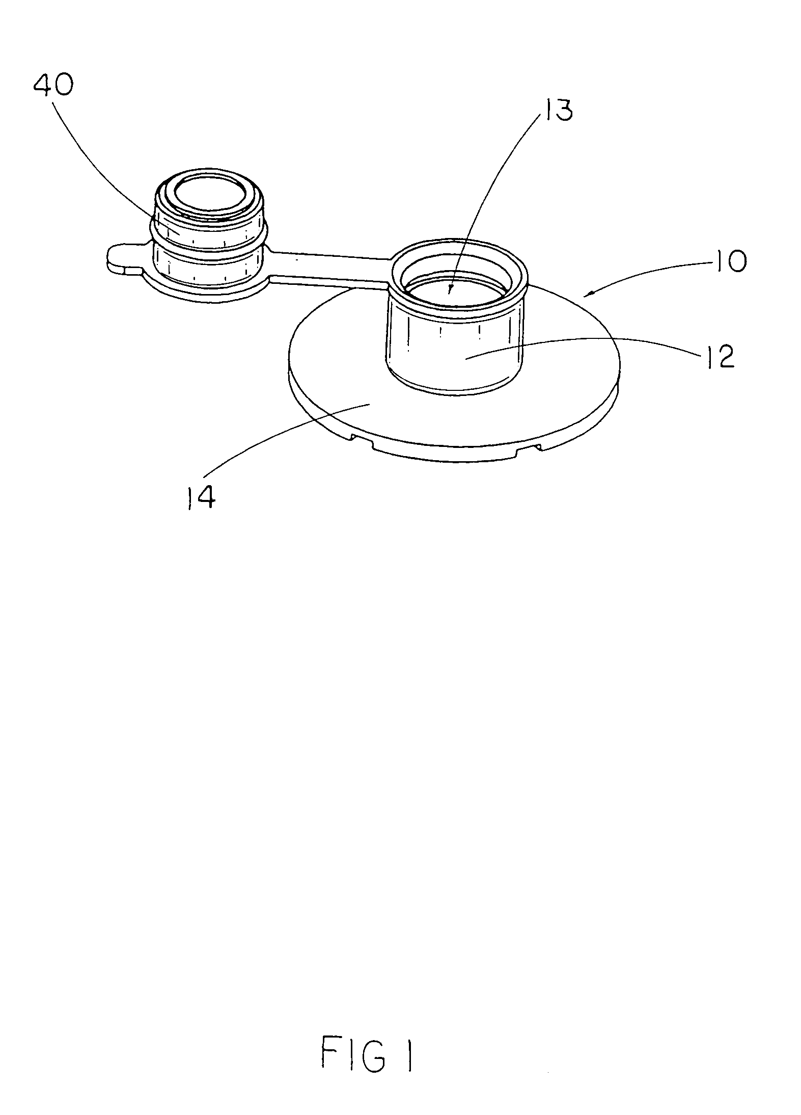
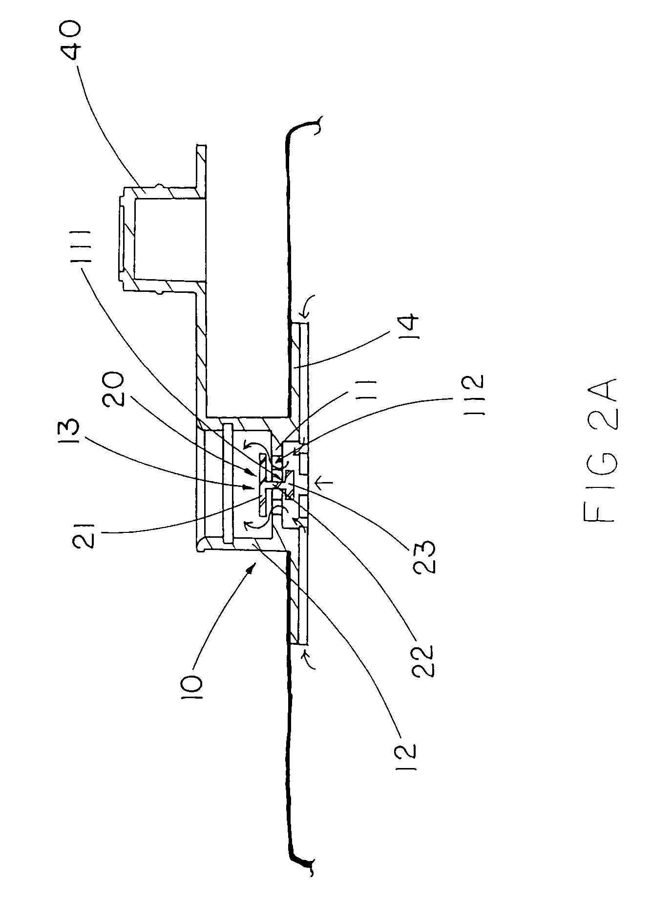
[0023]Referring to FIG. 1, FIG. 2A and FIG. 2B of the drawings, a vacuum pump valve of a container according to a first preferred embodiment of the present invention is illustrated, in which the container has a receiving cavity subject to an interior pressure, and an opening communicating with the receiving cavity. The vacuum pump valve comprises a valve body 10 and a suction element 20.

[0024]According to a first preferred embodiment of the present invention, the valve body 10 comprises a sealing platform 11 sealedly attached on the container at the opening thereof, and a guiding sleeve 12 upwardly extended from the sealing platform 11 to form a suction channel 13, wherein the sealing platform 11 has an operation hole 111 formed thereon at a position within the suction channel 13, and at least a through ventilating groove 112 communicating the receiving cavity of the container with an exterior thereof, which is subject to an exterior pressure.

[0025]On the other hand, the suction ele...


PUM


Abstract

A vacuum pump valve includes a valve body and a suction diaphragm. The valve body includes a sealing platform sealedly attached on the container at the opening thereof, and a guiding sleeve upwardly extended from the sealing platform to form a suction channel, wherein the sealing platform has an operation slot formed thereon at a position within the suction channel and at least a through ventilating groove communicating the receiving cavity of the container with an exterior thereof. The suction diaphragm is disposed within the suction channel of the valve body, including an enlarged sealing head adapted to seal on the sealing platform to enclose the ventilating groove thereof, and a guiding shaft extended from the sealing head to slidably mounted at the sealing platform at the operation slot to move the sealing head between a releasing position and a sealing position.

Description

BACKGROUND OF THE PRESENT INVENTION[0001]1. Field of Invention[0002]The present invention relates to a sealing valve, and more particularly to a vacuum pump valve which is capable of effectively sealing a particular container in a vacuum manner.[0003]2. Description of Related Arts[0004]Vacuum pumps have widely been utilized to extract air from a food container, such as a plastic bag, so as to create a vacuum environment within the container for preserving the food for a prolonged period of time. The basic steps for sealing a container is pretty simple: first, a vacuum pump is inserted into the container via a vacuum opening; second, a user may turn on the vacuum pump for extracting air within the container, third, the vacuum pump is detached from the container, finally, the vacuum opening should be effective sealed to prevent air going in or out of the container via the vacuum opening.[0005]As a matter of conventional practice, the latter step represents the most important factor in...

Claims


Application Information

Patent Timeline
Patent Type & Authority Patents(United States)
IPC IPC(8): B65D51/16
CPCF16K17/42F16K17/28Y10T137/2012Y10T137/792
Inventor CHEUNG, GEORGE F.
Owner INTELLI INNOVATIONS
Why Eureka
Try Eureka