

Droplet ejecting apparatus and ejection abnormality detecting/determining method for a droplet ejecting head
a technology of droplet ejection and abnormal detection, which is applied in the direction of breathing masks, breathing filters, breathing protection, etc., can solve the problems of inability to eject ink, high detector costs, image deterioration, etc., and achieve the effect of detecting the residual vibration period on the vibration plate more simply and correctly
- Summary
- Abstract
- Description
- Claims
- Application Information
AI Technical Summary
Benefits of technology
Problems solved by technology
Method used
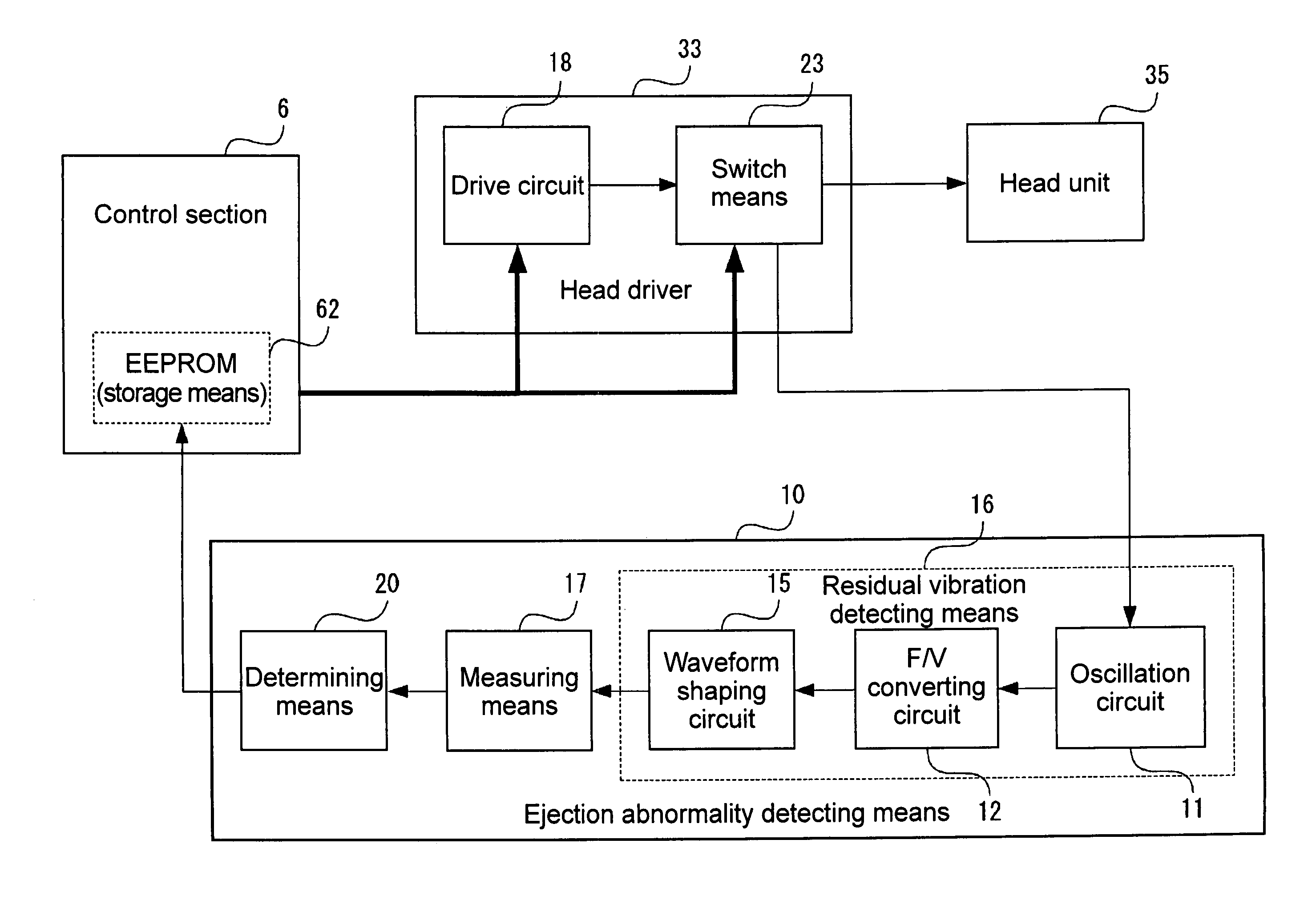
Image

Examples
first embodiment
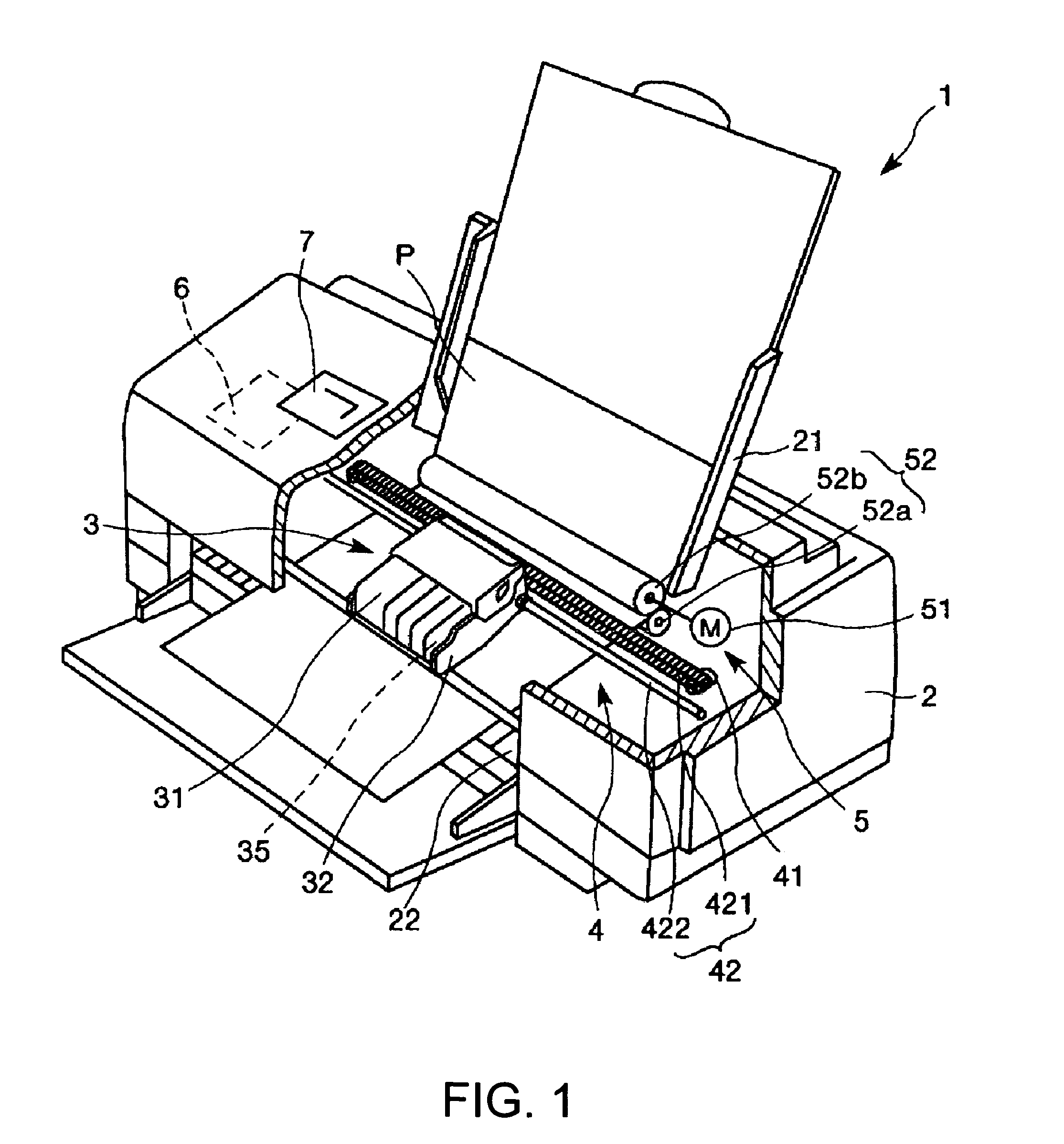
[0059]FIG. 1 is a schematic view showing a construction of an ink jet printer 1 as one example of a droplet ejecting apparatus according to a first embodiment of the present invention. Incidentally, in the following explanation, the upper side in FIG. 1 is referred to as the “upper” while the lower side therein is as the “lower”. At first, an explanation is made regarding the construction of the ink jet printer 1.
[0060]The ink jet printer 1 shown in FIG. 1 is provided with an apparatus main body 2 having a tray 21 in the upper rear thereof for placing a recording paper P, an exit port 22 in the lower front thereof for the recording paper P to exit, and an operation panel 7 in the upper surface thereof.
[0061]The operation panel 7 is configured, for example, by a liquid crystal display, an organic EL display, or an LED lamp, to have a display part (not shown) for displaying an error message, etc. and an operating part (not shown) structured by various switches and the like.
[0062]Meanw...
second embodiment
[0163]Now, explanation is made regarding another structural example of ink jet head of the present invention. FIGS. 27 to 30 are sectional views respectively showing the outlines of the other structural examples of the ink jet head 100. Although the explanation in the following is based on these figures, explanation is by centering on the difference from the foregoing embodiment while omitting explanations of similar matter.
[0164]An ink jet head 100A shown in FIG. 27 has a vibration plate 212 to be vibrated by the drive of a piezoelectric element 200, to eject the ink (liquid) within a cavity 208 through a nozzle 203. A stainless steel nozzle plate 202, formed with the nozzle (ports) 203, is bonded with a stainless steel metal plate 204 through an adhesive film 205, on which a similar stainless steel metal plate 204 is further bonded through an adhesive film 205. Furthermore, a communication-port-formed plate 206 and a cavity plate 207 are bonded thereon.
[0165]The nozzle plate 202, ...
PUM
 Abstract
Description
Claims
Application Information