Multileaf collimator for an X-ray diagnostic device

a diagnostic device and multi-leaf technology, applied in the direction of radiation beam directing means, diaphragms/collimeters, radiation diagnostic diaphragms, etc., can solve the problem of complex overall mechanical design, and achieve the effect of facilitating replacemen

Inactive Publication Date: 2006-09-19
SIEMENS AG
View PDF6 Cites 13 Cited by
  • Summary
  • Abstract
  • Description
  • Claims
  • Application Information

AI Technical Summary

Benefits of technology

[0004]An object of the invention is to provide a multileaf collimator for an X-ray diagnostic device that exhibits a particularly good balance between design complexity, physical size and technical beam properties.
[0006]In a preferred embodiment, at least four collimation planes in each case are located in front of or behind the mirror in the direction of radiation of the X-ray beam, in particular both on the side of the mirror facing the X-ray source, i.e. on the focus side, and on the side facing away from the X-ray source. Collimation in multiple planes, in total preferably in at least eight planes, for example in at least ten planes, has the advantage in particular of also being a highly effective means of filtering out secondary and tertiary radiation.
[0008]The described beam-limiting design employing collimator leaves that can be displaced and / or tilted, which is easy to produce, saves weight and space and requires minimum control complexity, can also be applied analogously to the light beam provided for identifying the X-ray beam.
[0010]Both the collimator leaves and, if applicable, the additional beam filters and / or additional leaves preferably have motorized adjustment. In addition, according to an advantageous development, the collimator leaves can be designed in such a way that the edge region of a collimator leaf, said region being used for limiting the X-ray beam, is also provided for producing a machine- or component-specific identification on the X-ray photograph, as known in principle from U.S. Pat. No. 5,923,725, for example. The compact design of the multileaf filter is retained even when including one or more of the additional features cited. Unlike a multileaf filter having solely tilting collimator leaves, these leaves can also be replaced far more easily.

Problems solved by technology

The multileaf collimator known from DE 34 36 866 C2 comprises a plurality of pairs of collimator leaves coupled by means of various gears, and its overall mechanical design is complex.

Method used


Image

  • Multileaf collimator for an X-ray diagnostic device
  • Multileaf collimator for an X-ray diagnostic device

Examples


Embodiment Construction

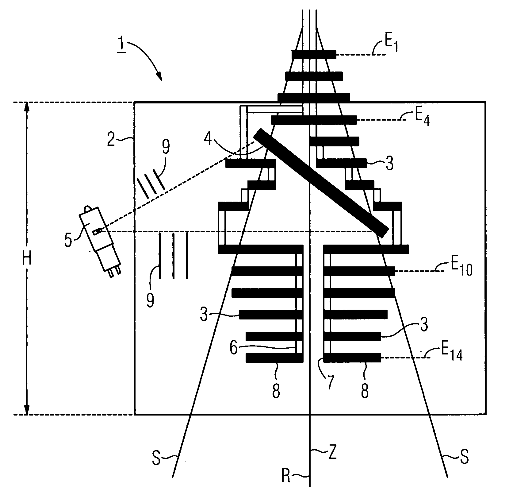
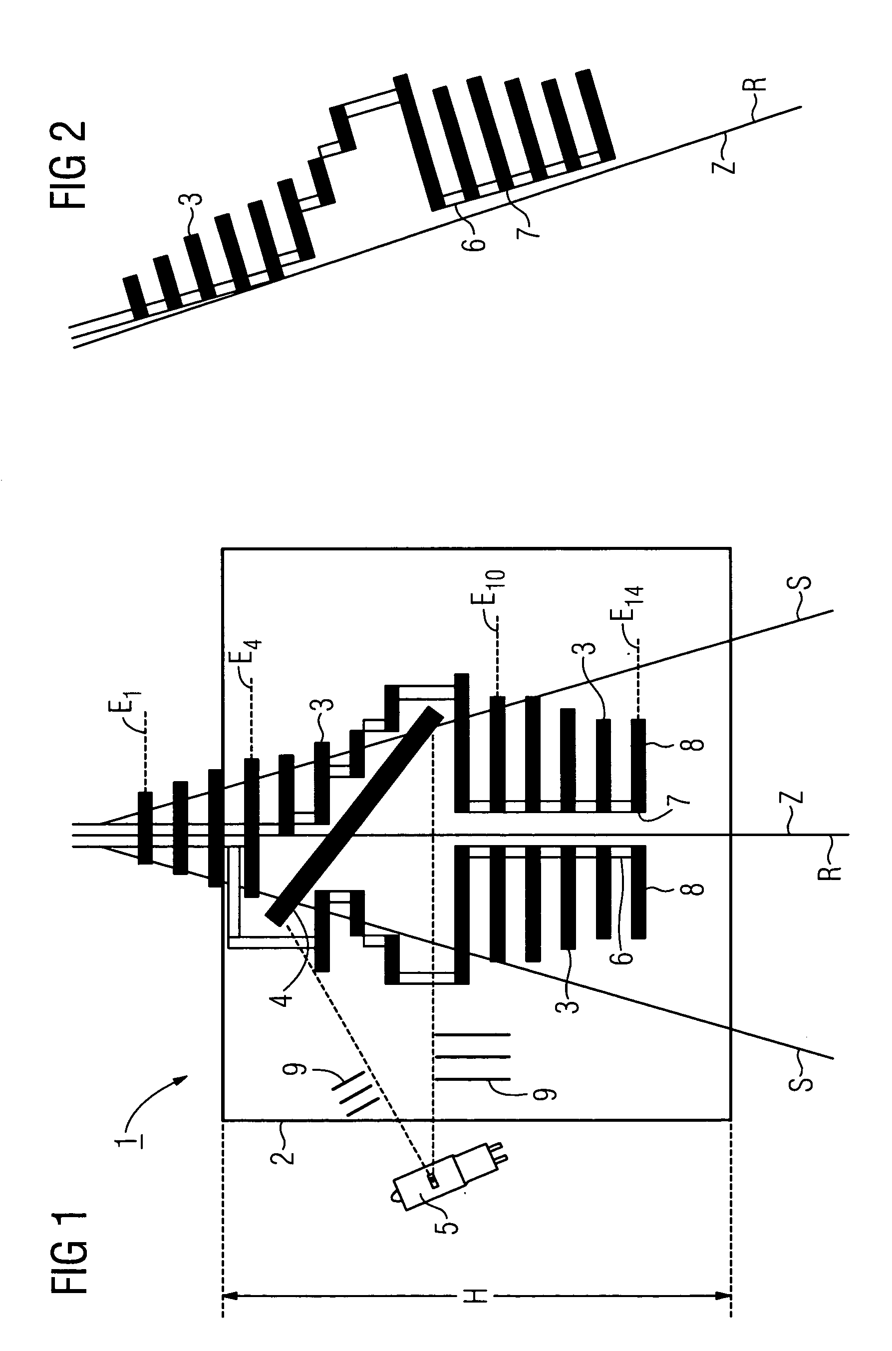
[0015]A multileaf collimator 1 shown symbolically in FIGS. 1 and 2 for a medical X-ray diagnostic device (not shown in further detail) comprises a housing 2, a plurality of collimator leaves 3, mostly arranged in pairs, a mirror 4 and a light source 5. The X-ray beam emitted from an X-ray source (not shown) is labeled with S, and the direction of radiation with R. In the cross-section shown in FIG. 1, the multileaf collimator 1, with the exception of the mirror 4, has a substantially symmetrical structure about the straight line given by the direction of radiation R. A light beam, indicated by dashed lines, emitted by the light source 5, is reflected by the mirror 4, which is effectively transparent to X-rays, thereby identifying by visible light the area to be examined by means of the X-ray beam S, in particular a patient to be examined. The multileaf collimator 1 is not restricted to medical applications, however, but can also be used in the field of material testing for example.

[...


PUM


Abstract

A multileaf collimator (1) of an X-ray diagnostic device has a housing (2) that is provided for the passage of an X-ray beam (S), collimator leaves (3) arranged in said housing for limiting the X-ray beam (S), and a light source (5) and a mirror (4) for identifying the X-ray beam (S) by visible light. A plurality of collimator leaves (3) at a time are arranged in front of the mirror (4) and behind the mirror (4) in the direction of radiation (R) of the X-ray beam (S), and are rigidly coupled together, the individual collimator leaves (3) each being arranged in collimation planes (E1–E14) which are orientated at least approximately normal to the direction of radiation (R) of the X-ray beam (S).

Description

CROSS REFERENCE TO RELATED APPLICATIONS[0001]This application claims priority to the German application No. 10 2004 009 897.2, filed Feb. 26, 2004 which is incorporated by reference herein in its entirety.FIELD OF INVENTION[0002]The invention relates to a multileaf collimator provided for an X-ray diagnostic device, an X-ray beam emitted from an X-ray source being limited by collimator leaves arranged in a housing of the multileaf collimator. The multileaf collimator also contains a mirror that can receive visible light from a light source and hence enables an identification of the X-ray beam. Such a multileaf collimator is known, for example, from DE 34 36 866 C2 or DE 24 24 619 A1.BACKGROUND OF INVENTION[0003]The multileaf collimator known from DE 34 36 866 C2 comprises a plurality of pairs of collimator leaves coupled by means of various gears, and its overall mechanical design is complex. Tilting collimator leaves are located in the beam path of the X-ray beam both in front of a...

Claims


Application Information

Patent Timeline
Patent Type & Authority Patents(United States)
IPC IPC(8): A61B6/08G21K1/02
CPCG21K1/025A61B6/08A61B6/06
Inventor SCHMITT, THOMAS
Owner SIEMENS AG
Why Eureka
Try Eureka