Fuel supply system installed inside fuel tank

Active Publication Date: 2006-09-19
DENSO CORP
View PDF7 Cites 12 Cited by
  • Summary
  • Abstract
  • Description
  • Claims
  • Application Information

AI Technical Summary

Benefits of technology

[0008]In view of the foregoing problems, the purpose of the present invention is to provide a fuel supply system having a pump unit that can be smoothly moved relatively to a cover of the fuel supply system.
[0009]According to the present invention, each supporting portion for supporting a corresponding metal pipe has a groove. The groove is formed in an inner periphery of the supporting portion, on which the metal pipe is slidably moved. Accordingly, when the metal pipe is leaned inside the supporting portion, the contacting areas of the metal pipe and the supporting portion are reduced, and thereby the sliding resistance between the metal pipe and the supporting portion is reduced. Therefore, each metal pipe can be smoothly moved in its axial direction inside the corresponding supporting portion, that is, the cover and the pump unit can be smoothly moved relatively to each other.

Problems solved by technology

In case the metal pipes and the supporting portions are made of the same material, noisy sounds are generated when the metal pipes are moved inside the supporting portion.
However, for example, when the metal pipes are made of metal, the solidity of which is high, and the supporting portions are made of resin, the solidity of which is low, sliding resistances between the metal pipes and the supporting portions are disadvantageously heightened.
However, depending on the shape of the fuel tank, or depending on the expansion or the contraction of the fuel tank, the axes of the metal pipes are not always disposed perpendicularly to an inner bottom surface of the fuel tank.

Method used


Image

  • Fuel supply system installed inside fuel tank
  • Fuel supply system installed inside fuel tank
  • Fuel supply system installed inside fuel tank

Examples


first embodiment

(First Embodiment)

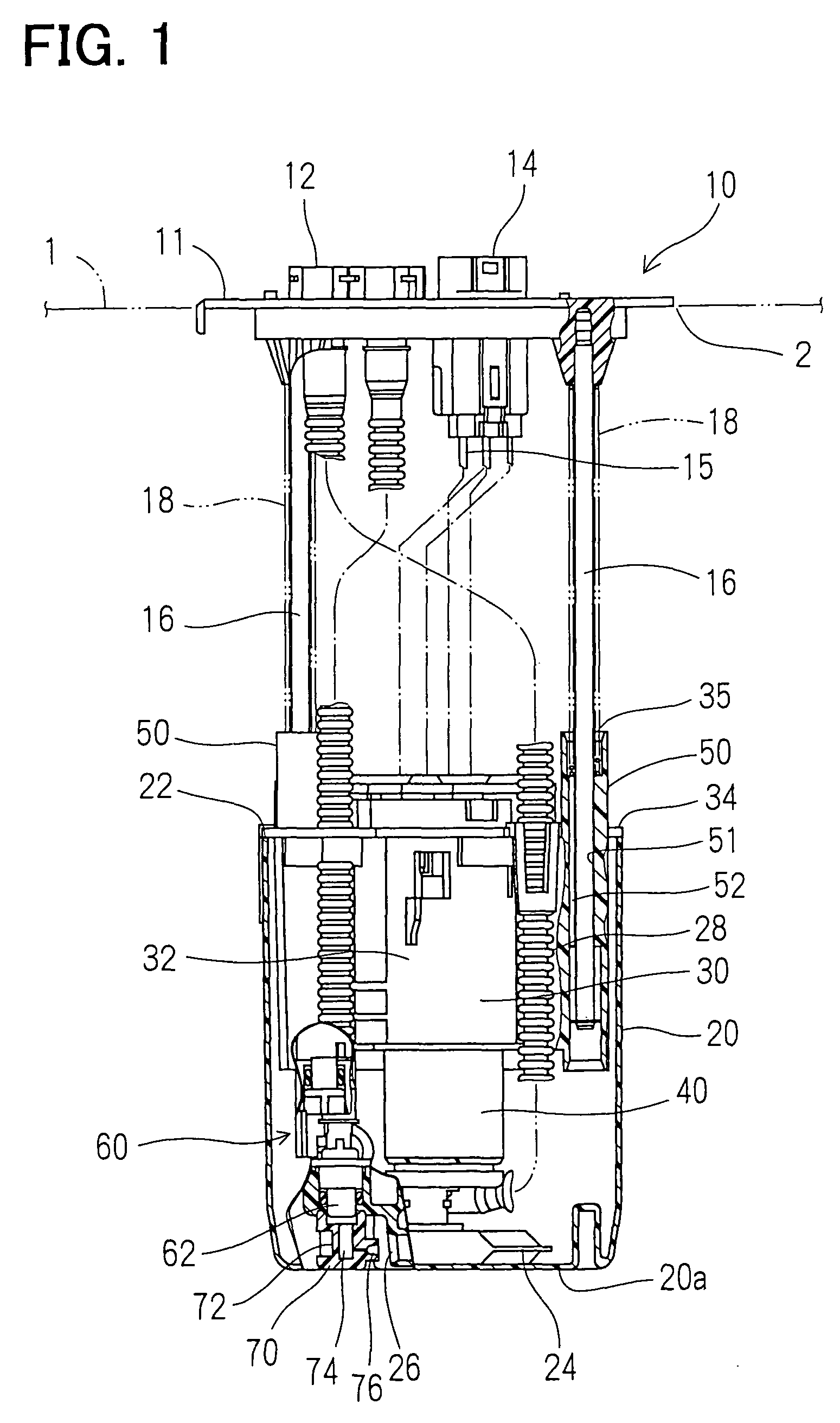
[0019]FIG. 1 shows a fuel supply system 10 according to the first embodiment of the present invention. The fuel supply system 10 has a disc-shaped cover (flange) 11. The cover 11 is fastened to an upper wall of an integrally resin-made fuel tank 1 (not shown) so that the fuel supply system 10 is installed inside the fuel tank 1. Except for the cover 11, covering an opening 2 of the fuel tank 1, components of the fuel supply system 10 are stored inside the fuel tank 1.

[0020]The cover 11 has a fuel outlet 12 and an electric connector 14. Fuel stored in a fuel pump 40, installed inside a sub-tank 20, is discharged through the fuel outlet 12 into outside of the fuel tank 1. Electricity is supplied to the fuel pump 40 from the electric connector 14 through lead wires 15.

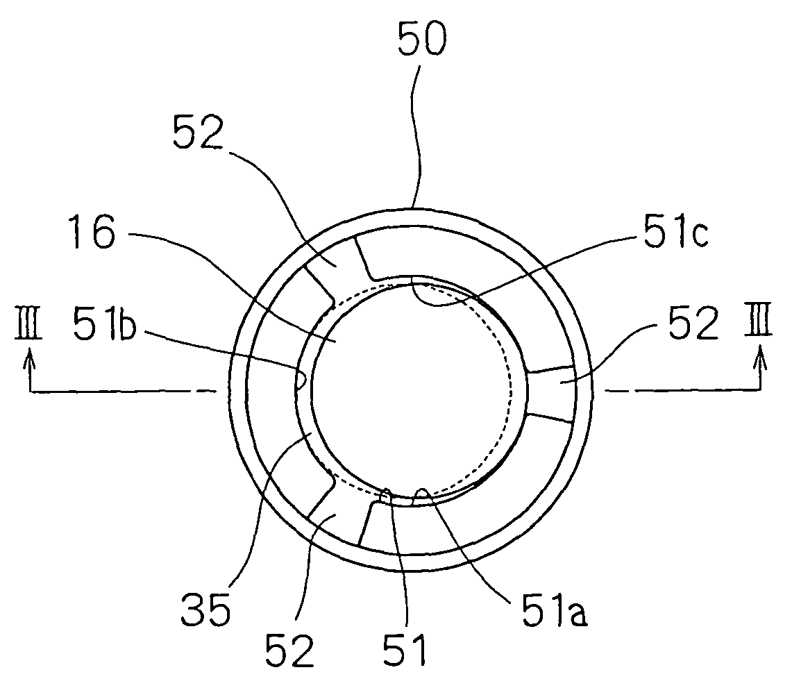
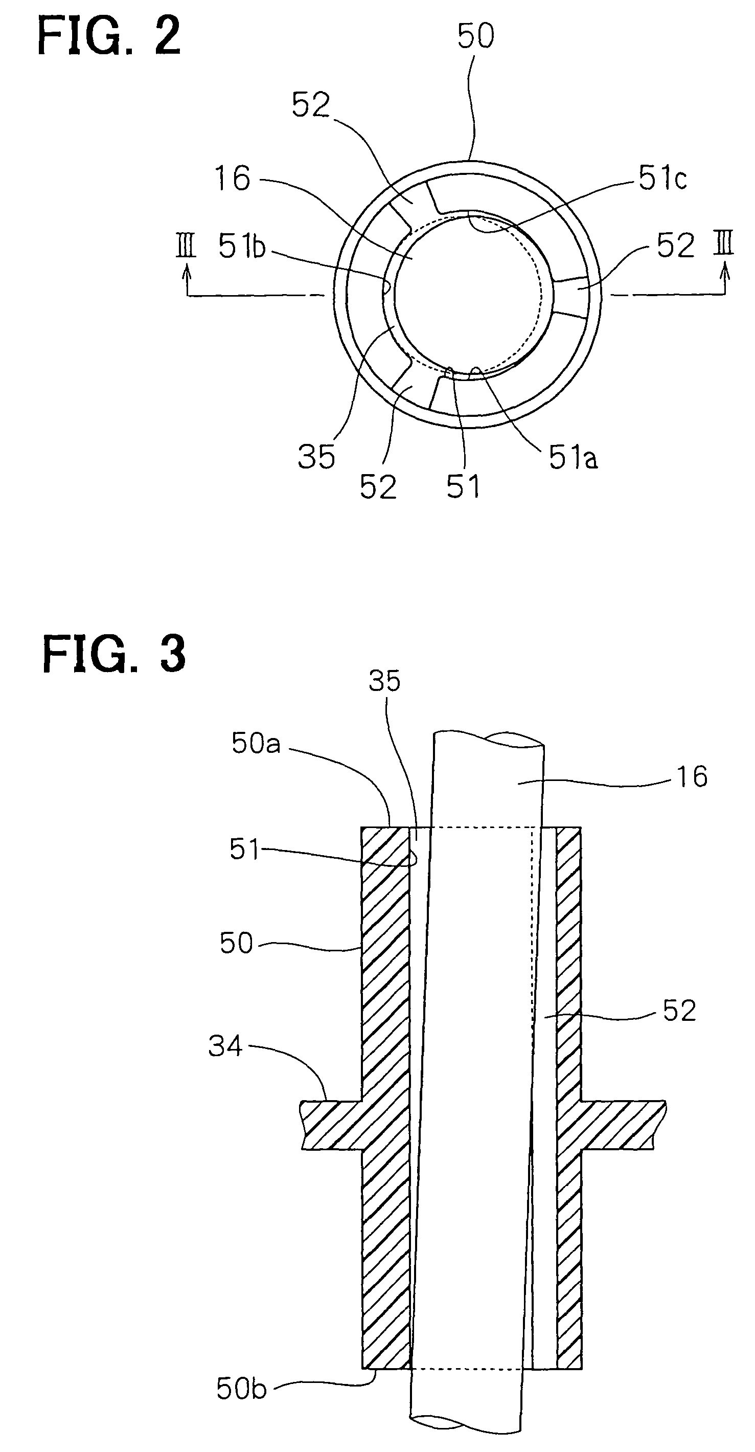
[0021]The cover 11 and a case cover 34 are connected by metal pipes 16, which are made of, for example, stainless steel or aluminum. One end of each metal pipe 16 is fastened to the cover 11, and the oth...

second embodiment

(Second Embodiment)

[0033]FIG. 5 shows a fuel supply system 10 according to the second embodiment of the present invention. The components of the second embodiment essentially the same as those of the first embodiment are indicated by the numerals the same as the first embodiment, and the further explanations of which are abbreviated.

[0034]A fuel supply system 10 according to the second embodiment of the present invention includes a cover 11 and a pump unit. The pump unit is supported by metal pipes 161, 162, the ends of which are fixed in the cover 11, movably in the axial direction of the metal pipes 161, 162. The pump unit includes a sub-tank 20, a fuel filter 30 and a fuel pump 40. The fuel filter 30 and the fuel pump 40 are stored inside the sub-tank 20 having a bottom.

[0035]As shown in FIG. 6, the sub-tank 20 has a substantially cylindrical shape and two recesses 21. The recesses 21 are disposed at substantially the same intervals around the circumference of the sub-tank 20. Su...


PUM


Abstract

A fuel supply system has a cover, a pump unit, and metal pipes. The cover and the pump unit are connected through the use of the metal pipes so as to be moved relatively each other. A case cover, covering the pump unit, has supporting portions, each of which has a through hole. Each metal pipe is inserted through the through hole and thereby guided to be moved in its axial direction inside the supporting portion. The supporting portion has a plurality of grooves. Therefore, sliding resistance between the metal pipe and the supporting portion is reduced, that is, the pump unit can be smoothly moved relatively to the cover.

Description

CROSS REFERENNCE TO RELATED APPLICATION[0001]This application is based on Japanese Patent Applications No. 2002-241683 filed on Aug. 22, 2002 and No. 2003-184586 filed on Jun. 27, 2003, the disclosures of which are incorporated herein by reference.FIELD OF THE INVENTION[0002]The present invention relates to a fuel supply system installed in a fuel tank.BACKGROUND OF THE INVENTION[0003]A fuel supply system installed in a fuel tank is, for example, described in a patent document of JP-A-H11-101166. This fuel supply system has a cover, a pump unit and metal pipes. The cover is fastened to an opening of a fuel tank. The cover and the pump unit are connected through the use of the metal pipes, and thereby the pump unit is stored inside the fuel tank. The pump unit has a fuel pump, which is stored in a sub-tank to be installed inside the fuel tank. Moreover, the cover and the pump unit are biased by springs so as to be drawn apart each other. One end of each metal pipe is fastened to the ...

Claims


Application Information

Patent Timeline
IPC IPC(8): F04B17/00F04B35/00F02M37/00F02M37/10
CPCF02M37/103F02M37/106
Inventor KOBA, TAKASHIYAMASHITA, KEIICHISAKAI, TATSUO
Owner DENSO CORP
Why Eureka
Try Eureka