Drain inlet

a technology of drain inlet and drain pipe, which is applied in the direction of sewage draining, water cleaning, sewer cleaning, etc., can solve the problems of reducing the flow volume of water being drained, debris in water, and the efficiency of such relatively tall drain inl

Active Publication Date: 2006-09-19
PLASTIC DESIGNS
View PDF13 Cites 43 Cited by
  • Summary
  • Abstract
  • Description
  • Claims
  • Application Information

AI Technical Summary

Benefits of technology

[0006]The drain inlet of the present invention overcomes these several disadvantages of the last mentioned prior cylindrical upstanding drain pipe inlets. In the present invention water to be drained from an area flows upwardly into the drain inlet of the present invention through a plurality of elongated slots in laterally extending walls which separate adjacent side walls of the body of the drain inlet. The total cross sectional area of the slots is at least as great and preferably greatly exceeds the cross sectional area of the discharge from the drain inlet of the invention. This insures that the water flow volume into the drain inlet of the present invention is at least as great as the flow volume which can be discharged from the drain inlet even if some of the openings might become non-functional for one reason or another. Also because of the large cross sectional area of the slots, the flow rate though the slots is substantially reduced, thereby minimizing the collection of debris at the slots and the clogging of the slots by such debris. Thus, less time and hassle is involved in wading out into ponds to clean debris out of the openings than was needed with the relatively small holes of the prior drain inlets which was a nuisance and unpleasant task often done under very cold and wet conditions. Moreover, faster drainage of the standing water may be accomplished which is better for the crops and the soil. Also, because of the ability of the present invention to substantially maximize the flow volume through the drain inlet, it is no longer necessary as in the prior art that the drain inlet body stand as tall as it must to insure adequate flow volume. Therefore, the height of the drain inlet may be substantially shortened to a height which may be easily avoided by, for example combines during harvest most of which have heads which can be elevated three or more feet above the level of the ground. Still another advantage of the positioning of the openings in the drain inlet of the present invention in laterally extending walls is that the flow of the liquid from the pond into the drain inlet is upward, and any debris that may be trapped on the downwardly facing openings tends to fall away by gravity both during the draining procedure and after the pond has been drained. Thus, the openings of the drain inlet of the present invention are relatively self cleaning. Still another advantage of the present invention is that the amount of residue or debris that enters the buried drain tile is substantially reduced. This reduces the amount of BOD and nitrates in the water and the possibility of potential clogging and need to clean out or replace the buried drain tile.
[0007]In one principal aspect of the present invention, a drain inlet for draining a fluid from an area comprises a body having a chamber therein for receiving the fluid from the area and an opening adjacent the bottom of the body for draining the fluid from the chamber. At least two side walls form the body and are spaced from each other in the direction of the height of the body, the side wall closest to the opening adjacent the bottom of the body being smaller in lateral cross section than the lateral cross section of the next adjacent side wall which is farther from the opening. A wall extends laterally between the two side walls, and an opening is positioned in the laterally extending wall, whereby the fluid flows upwardly through the opening in the laterally extending wall and into the chamber, and out of the chamber through the opening adjacent the bottom of the body to drain the area of the fluid.
[0008]In another principal aspect of the present invention, a plurality of the openings are located in the laterally extending wall.
[0009]In still another principal aspect of the present invention, the total cross sectional area of the openings in the laterally extending wall is at least as great as the cross sectional area of the opening adjacent the bottom of the body.
[0010]In still another principal aspect of the present invention, the opening in the laterally extending wall is an elongate slot.
[0011]In still another principal aspect of the present invention, an upstanding member is positioned around the opening in the laterally extending wall.

Problems solved by technology

However, even if not plugged by debris, such prior screening devices generally reduce the flow volume of the water being drained at any given time from the potential flow volume which could be drained without the screen or grate.
This results in debris in the water which is to be drained to be drawn to and cover the holes due to the suction produced by the high flow rate through the holes.
Moreover, the efficiency of such relatively tall pipe drain inlets is further diminished as the water level drops in the area being drained, because the water level will drop below the drain holes in the upper part of the pipe and, therefore, those holes will no longer function to provide drainage.
Another disadvantage of these relatively tall prior pipe drain inlets is that they must be avoided during seeding and harvesting and it is generally necessary to seed and harvest around them because seeders and harvester combines cannot be elevated to a sufficient height during seeding and harvest to be able to pass over the relatively tall drain pipes.
Thus, less time and hassle is involved in wading out into ponds to clean debris out of the openings than was needed with the relatively small holes of the prior drain inlets which was a nuisance and unpleasant task often done under very cold and wet conditions.

Method used


Image

  • Drain inlet
  • Drain inlet
  • Drain inlet

Examples


Embodiment Construction

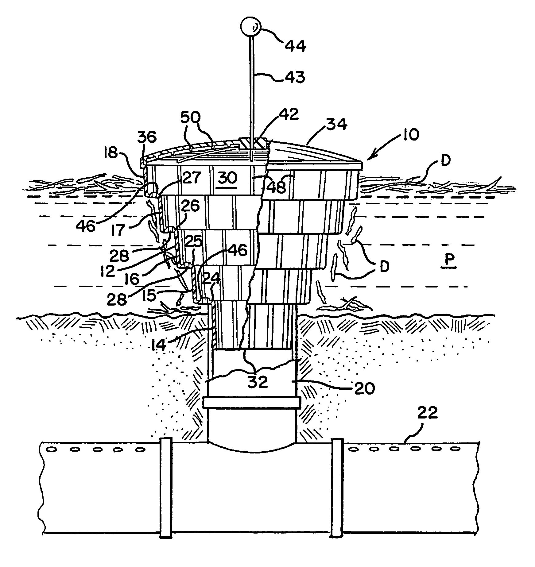
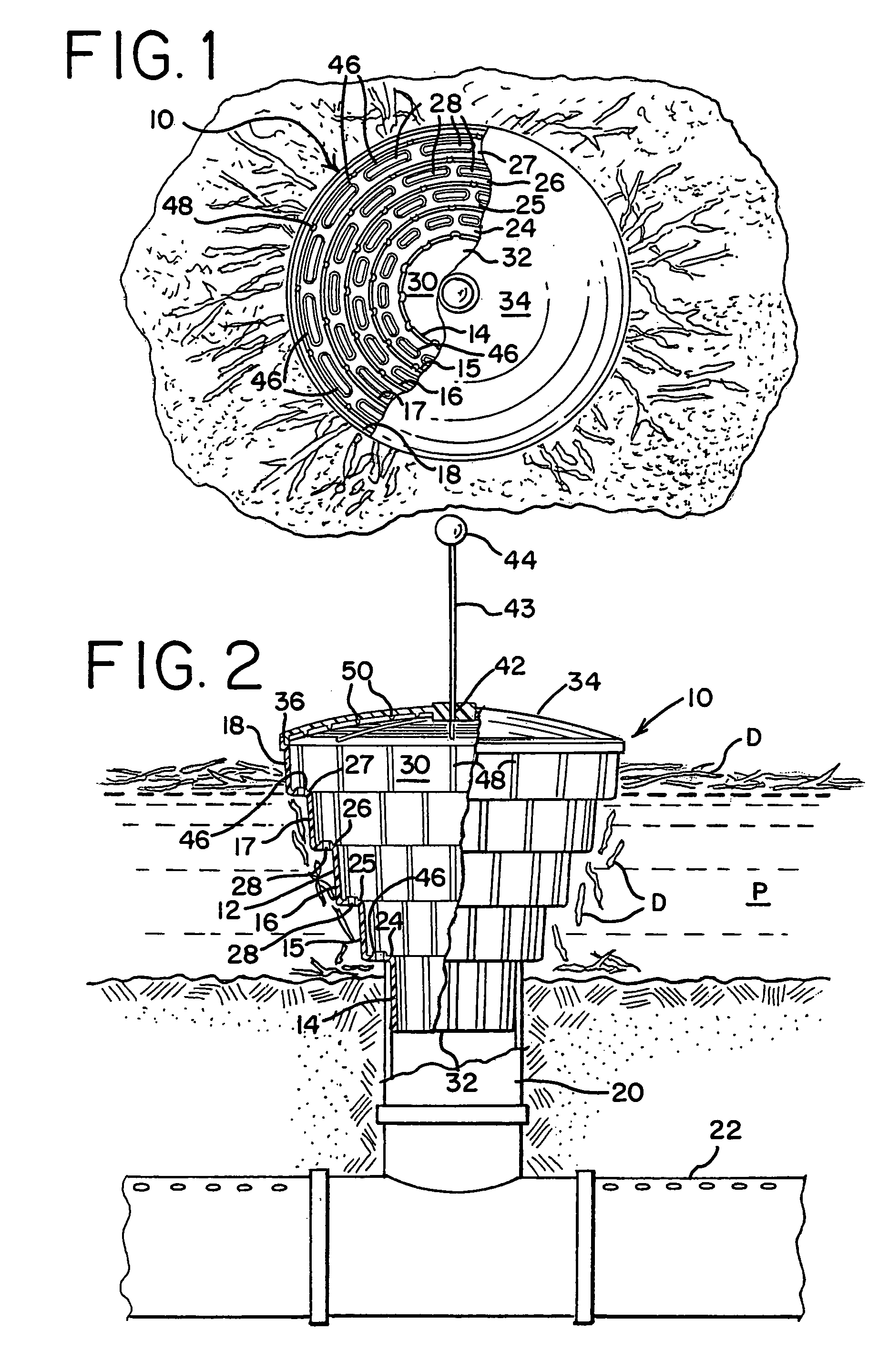
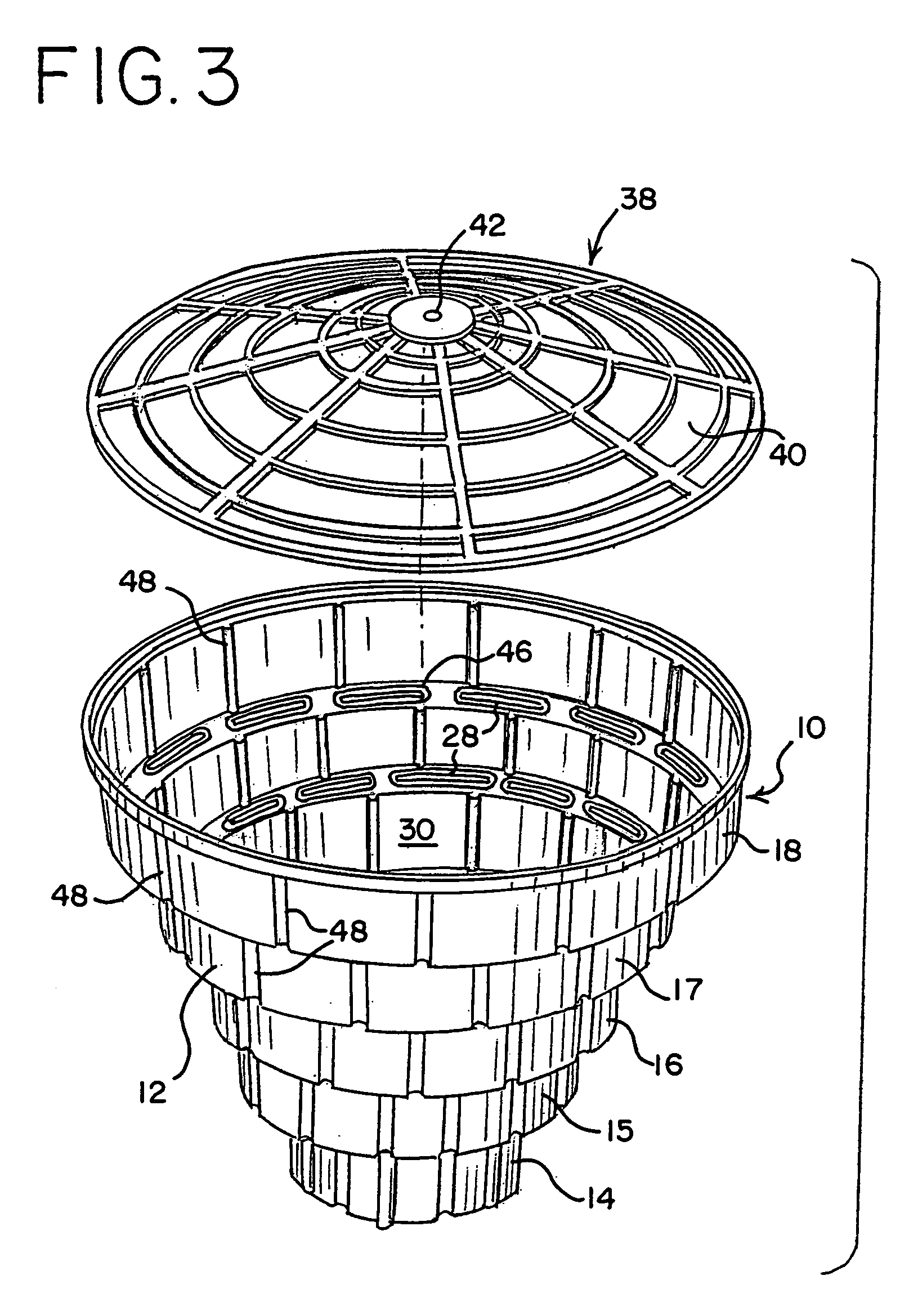
[0026]With particular reference to FIGS. 1 and 2, a preferred embodiment of drain inlet 10 of the present invention comprises a generally upstanding body 12 formed of a plurality of generally upwardly extending side walls 14, 15, 16, 17 and 18. The bottommost side wall 14 is preferably tapered to be slightly smaller toward its bottom to enable it to be press fit into the opening in the upstanding inlet 20 of a drain tile 22 which is installed beneath pond P to be drained, as best seen in FIG. 2. The drain tile 22 may either be unperforated or perforated as shown in FIG. 2. The remaining side walls 15–18 also extend upward either vertically or at a slight angle to the vertical.

[0027]The construction of the body 12 is completed by generally horizontal steps which are formed by walls 24, 25, 26 and 27 which extend laterally between the top of the next lower adjacent side wall and the bottom of the next upper adjacent side wall. Although as shown in the drawing the walls 24–27 extend ge...


PUM


Abstract

A drain inlet is disclosed for draining of liquid from an area in which it has collected. The inlet includes a body having a chamber therein for receiving the liquid from the area and an opening at the bottom of the body for draining the liquid from the chamber. The body is formed by a plurality of side walls each of which has a lateral cross section which is greater than the next adjacent lower side wall which permits a substantial reduction in the height of the body. The bottom of the side walls is connected to the top of the next lower side wall by a laterally extending wall which has a plurality of elongated slotted openings so that the fluid to be drained flows upwardly through these openings, into the chamber and out of the chamber through the opening at the bottom of the body to drain the area. The total cross sectional area of the openings in the walls through which the liquid flows is at least as great and preferably substantially greater than the cross sectional area through the opening at the bottom of the body which results in a substantial reduction in clogging of the openings by debris which may be present in the liquid being drained.

Description

BACKGROUND AND SUMMARY OF THE INVENTION[0001]The present invention is directed to a drain inlet for draining a fluid from an area.[0002]It is frequently desirable to drain fluids, such as standing water from areas in which it accumulates for example during wet weather in the spring or during periods of flood. For example, it is desirable to drain the water from low spots or terraces in agricultural fields to improve the crops and / or the soil when drained.[0003]In the past, such drainage has been accomplished by way of drain tile which is buried beneath the surface of the soil and upstanding inlets which are spaced periodically along the length of the tile and which open above the soil surface and into the area where the water has accumulated to drain the area through the buried drain tile. In such systems some form of grate or screen is usually positioned at the opening to the upstanding drain tile inlet in order to prevent debris which may be in the water from flowing through the i...

Claims


Application Information

Patent Timeline
Patent Type & Authority Patents(United States)
IPC IPC(8): E03F5/06
CPCE03F5/0404E03F1/00
Inventor GLAZIK, GARY B.
Owner PLASTIC DESIGNS
Why Eureka
Try Eureka