
Multi-color infrared imaging device

a multi-color, infrared technology, applied in the direction of radiation controlled devices, optical radiation measurement, instruments, etc., can solve the problems of unfavorable multi-color ir display, unnecessarily complex structure, and inability to collect ir images simultaneously in more than one band

Inactive Publication Date: 2006-09-19
UNITED STATES OF AMERICA THE AS REPRESENTED BY THE SEC OF THE ARMY
View PDF12 Cites 51 Cited by
  • Summary
  • Abstract
  • Description
  • Claims
  • Application Information

AI Technical Summary

Benefits of technology

Enables simultaneous collection of IR images in two LWIR bands and one MWIR band from the same point in space with maintained spatial resolution, simplifying manufacturing and reducing complexity compared to three-layer structures.

Problems solved by technology

The disadvantage of this method, however, is that the IR image cannot be collected simultaneously in more than one band.
Thus, this method of providing a multi-color IR display is not particularly useful if either the imaged object or platform sensor, or both, is in motion.
The result of the invention of Stokes, however, is an unnecessarily complex structure with three detection layers, each one optimized for a different band.
Stated differently, and as mentioned above, the device recited by Stokes requires the deposition of extra detector and deposition layers and does not solve the ease of manufacturing question, in that it would also be very difficult and expensive to build.

Method used


Image

  • Multi-color infrared imaging device
  • Multi-color infrared imaging device
  • Multi-color infrared imaging device

Examples


Embodiment Construction

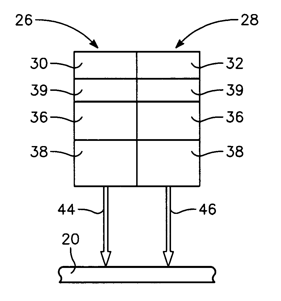
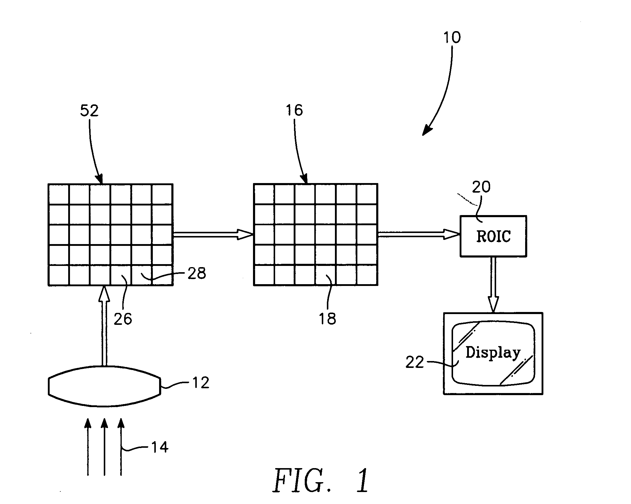
[0019]Throughout this specification, the terms IR, MWIR, LWIR, as well as the M, L1 and L2 are used. The term IR refers to infrared radiation, or that portion of the electromagnetic spectrum having a wavelength between 0.8 and 100 microns (λ=0.8–100 μm). The term MWIR refers to mid-wave infrared radiation, or that portion of the IR spectrum between three to seven micrometers (λ=3–7 μm), and the M band refers to MWIR between three to five micrometers (λ=3–5 μm). The term LWIR refers to long-wave infrared radiation LWIR radiation in the range of seven to ten microns (λ=7–12 μm). Within the LWIR range, two bands are defined, the L1 band (λ=7–9 μm) and the L2 band (λ=9–10 μm). Within the respective MWIR and LWIR ranges, other M, L1 and L2 bands can also be defined to practice the invention as hereinafter described.

[0020]Referring initially to the FIG. 1, the multi-color IR imaging device of the present invention is shown and is generally designated by reference character 10. The device ...


PUM


Abstract

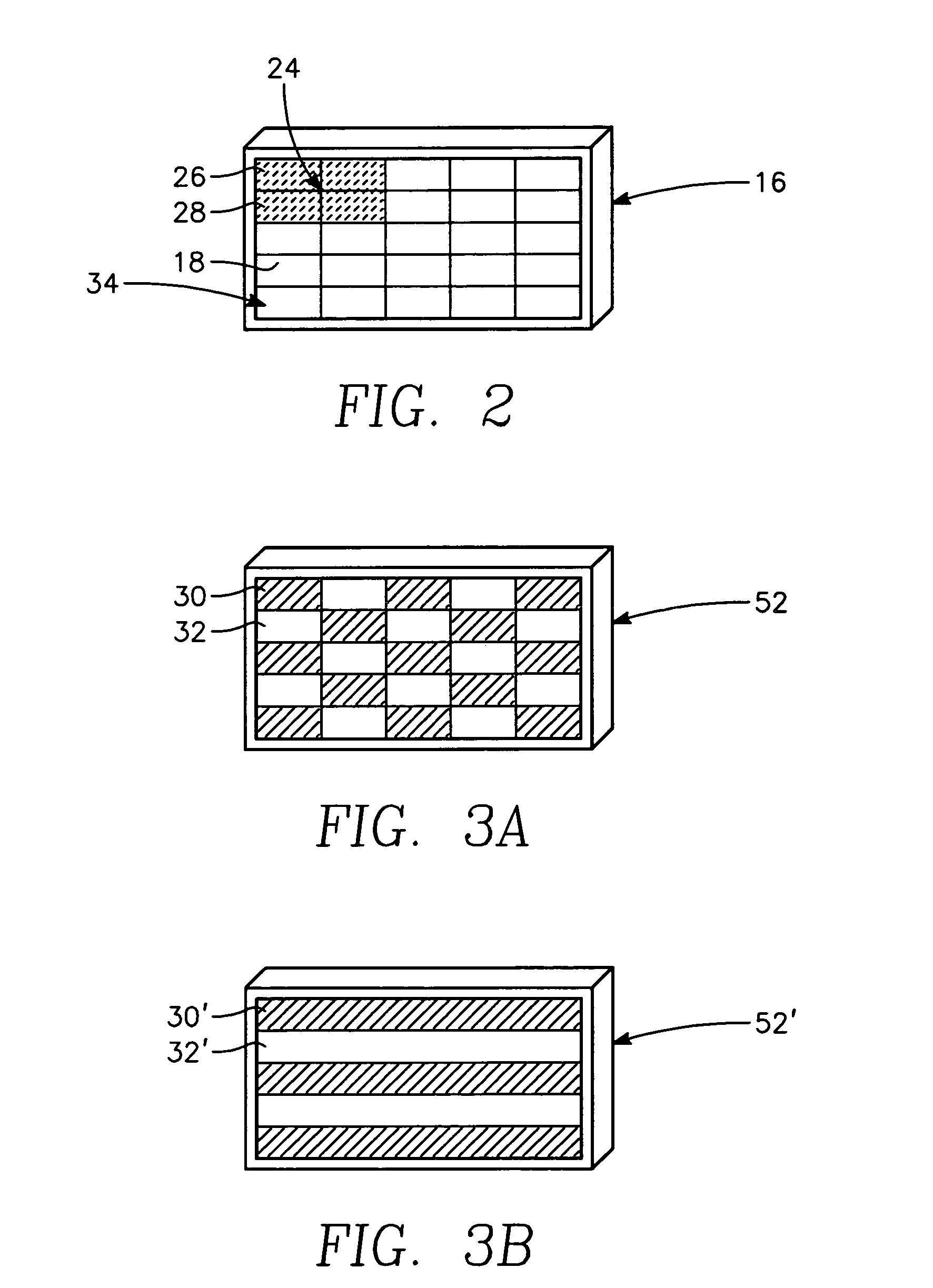
A multi-color IR imaging device includes optics that direct mid-wave infrared (MWIR) and long-wave infrared (LWIR) radiation onto a focal plane array having LWIR and MWIR detection layers. Pixel groups that include at least one first pixel and one second pixel are defined on the focal plane array, and a first filter and a second filter which form part of an inhomogeneous filter is placed over the respective first and second pixels in a checkerboard pattern, in close proximity to the detection layers. This allows MWIR radiation in M band, and LWIR radiation in an L1 band to pass therethrough and illuminate the first pixels, and M, L1, and a separate LWIR band designated L2 to pass therethrough and illuminate the second pixels. To simultaneously image both MWIR and LWIR, the focal plane array is placed at a predetermined distance from the optics so that the MWIR spot size covers a single pixel and the LWIR spot size is about the same area as the area of a group of two first pixels and two second pixels. Since all pixels receive the M band, half of the pixels in the group receive the L1 band, and the other half receives the L2 band, three bands can be generated. This allows simultaneous imaging of MWIR and two sub-bands of the LWIR from the same point in space.

Description

GOVERNMENT INTEREST[0001]The invention described herein may be manufactured, used, sold, imported, and / or licensed by or for the Government of the United States of America.FIELD OF THE INVENTION[0002]The present invention applies generally to infrared (IR) imaging systems. More particularly, the present invention applies to an IR imaging system that provides for simultaneous collection of IR image data in two long-wave infrared (LWIR) bands and one mid-wave infrared (MWIR) band without significant loss of spatial resolution of the received image.BACKGROUND OF THE INVENTION[0003]Infrared (IR) imaging sensors for displaying information are well known in the prior art. For some applications, IR sensors are used to distinguish an object from its background, and image data from several spectral bands is often useful for this application. The IR spectrum can be divided into mid-wave infrared (MWIR) and long-wave infrared (LWIR) bands, and prior art IR imaging systems typically are capable...

Claims


Application Information

Patent Timeline
Patent Type & Authority Patents(United States)
IPC IPC(8): H01L25/065G01J3/51G01J5/28H01L27/146H01L31/0232H01L31/09
CPCH01L27/14621H04N5/332H04N5/33H01L27/14649H01L27/14603H04N23/20H04N25/131H04N23/11
Inventor MILTON, A. FENNER
Owner UNITED STATES OF AMERICA THE AS REPRESENTED BY THE SEC OF THE ARMY
Learn More