System for displaying image, method for displaying image and program thereof

a technology for displaying systems and images, applied in the field of image display systems, image display methods and programs, can solve problems such as blur of front edges, tailing of rear edges, and multiple defects in motion objects, and achieve the effect of improving the quality of motion pictures displayed

Inactive Publication Date: 2006-09-19
LINKEDIN
View PDF16 Cites 7 Cited by
  • Summary
  • Abstract
  • Description
  • Claims
  • Application Information

AI Technical Summary

Benefits of technology

[0019]In view of the foregoing and other problems, drawbacks, and disadvantages of the conventional methods and structures, a feature of the present invention is to provide a method and structure for improving the quality of a motion picture displayed on a so-called “hold-type display”.
[0020]Another purpose of the present invention is to suppress the blur of the front edge, the tailing of the rear edge, the lowering of the brightness, and the perception of delay at the front edge or center position of an object, which are caused by properties of an afterglow reflected on a human retina when tracking a motion image such as a motion picture (hereinafter, sometimes abbreviated as “a motion picture”). Such suppression is carried out by modifying the brightness V of the object by use of a wave with a wavelength S in the case where the moving speed of the object is S when the motion picture is displayed particularly on the hold-type display.
[0035]Here, preferably, the program further includes a function for allowing the computer to recognize the moving speed of the motion object such that the created modification information includes information varied depending on the recognized moving speed, so that an image with a blur or the like can be improved.

Problems solved by technology

In the case of displaying a motion picture in such a manner, in the display devices other than an impulse-type display such as the CRT, several defects occur with regard to an object in motion due to an effect of a so-called “light-stimulus integration” (properties of an afterglow reflected on a human retina when following a motion picture).
Such defects include a blur of the front edge, a tailing of the rear edge, a lowering of the brightness, and a delay of the perceived position on the front edge or a center position.
Moreover, there occurs a center delay of S / 2 for a position in the screen coordinate system at the time of starting the next frame.
However, for example with regard to the OLED, the light emission efficiency is low, and the brightness is lowered if the blanking is employed therefor, thereby lowering the contrast.

Method used


Image

  • System for displaying image, method for displaying image and program thereof
  • System for displaying image, method for displaying image and program thereof
  • System for displaying image, method for displaying image and program thereof

Examples


Embodiment Construction

[0052]Referring now to the drawings, and more particularly to FIGS. 1–8(b), there are shown exemplary embodiments of the method and structures according to the present invention.

Exemplary Embodiment

[0053]The present invention will be described in detail based on an embodiment shown in the accompanying drawings.

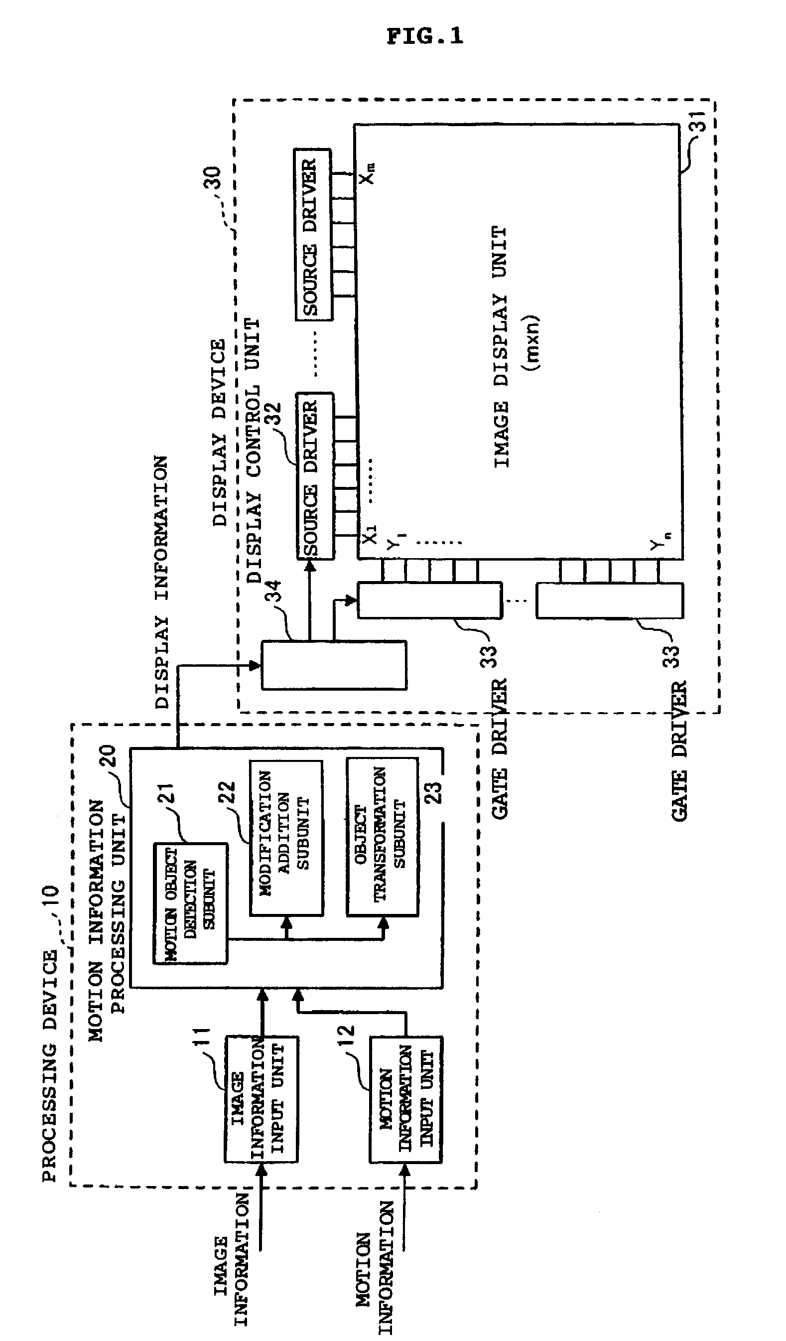
[0054]FIG. 1 is a diagram showing the entire configuration of an image display system to which this exemplary embodiment is applied.

[0055]The image display system shown in FIG. 1 includes the processing device 10 for processing image information obtained from a host side and outputting display information, and the display device 30 for actually displaying an image based on the image information obtained from the processing device 10.

[0056]Here, the “system” means a logical aggregation of a plurality of devices (functions), which has no relation to whether the devices (functions) of the constituent components exist in the same case or not. Accordingly, for example, similarly to...


PUM

PropertyMeasurementUnit
response timeaaaaaaaaaa
timeaaaaaaaaaa
moving speedaaaaaaaaaa

Abstract

A system (method and program for storing the method) for displaying an image, includes a motion object detector for detecting a motion object in image information inputted to the system, a recognizing device for recognizing a moving state in the motion object detected by the motion object detector, a modification information adder for adding modification information to the image information in regard to the motion object detected by the motion object detector based on the moving state recognized by the recognizing device, and a display device for displaying the image information having been added with the modification information by the modification information adder.

Description

BACKGROUND OF THE INVENTION[0001]1. Field of the Invention[0002]The present invention generally relates to an image display system, an image display method and a program, which are for displaying an image, and more specifically, to an image display system, an image display method and a program that improve quality of an image moving on a display.[0003]2. Description of the Related Art[0004]In recent years, among display devices, a liquid crystal display (LCD) provided with thin film transistors (TFT) has continued to develop greatly from viewpoints of its reduction in weight, thinness, portability, low power consumption and so on. Such an LCD is a display utilizing a property of liquid crystals, in which a molecular alignment is changed by applying a predetermined voltage thereto.[0005]Moreover, an organic light emitting diode (OLED) (also called “an organic EL”) has attracted attention as a next-generation display device. The OLED is a device for emitting light by flowing a direct ...

Claims


Application Information

Patent Timeline
Patent Type & Authority Patents(United States)
IPC IPC(8): G09G3/20G02F1/133G09G3/30G09G3/32G09G3/36G09G5/00G09G5/36H04N5/66
CPCG09G3/3225G09G3/3648G09G5/006G09G2300/0417G09G2320/106G09G2320/02G09G2320/0261G09G2320/103G09G2310/04
Inventor SEKIYA, KAZUONAKAMURA, HAJIME
Owner LINKEDIN
Why Eureka
Try Eureka