Door catch

a door and latch technology, applied in the field of door latches, can solve the problems of requiring a relatively high manufacturing cost, and achieve the effects of reducing the manufacturing cost, eliminating the drawbacks, and being easy to assemble and mount without the risk of loosening and/or separation of insert plates

Inactive Publication Date: 2006-09-26
HSU MING PIAO
View PDF10 Cites 18 Cited by
  • Summary
  • Abstract
  • Description
  • Claims
  • Application Information

AI Technical Summary

Benefits of technology

[0005]The primary purpose of the present invention is to provide an improved door catch to eliminate the drawbacks existing in the conventional door catches.
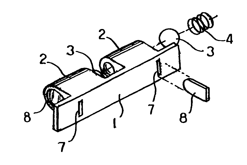
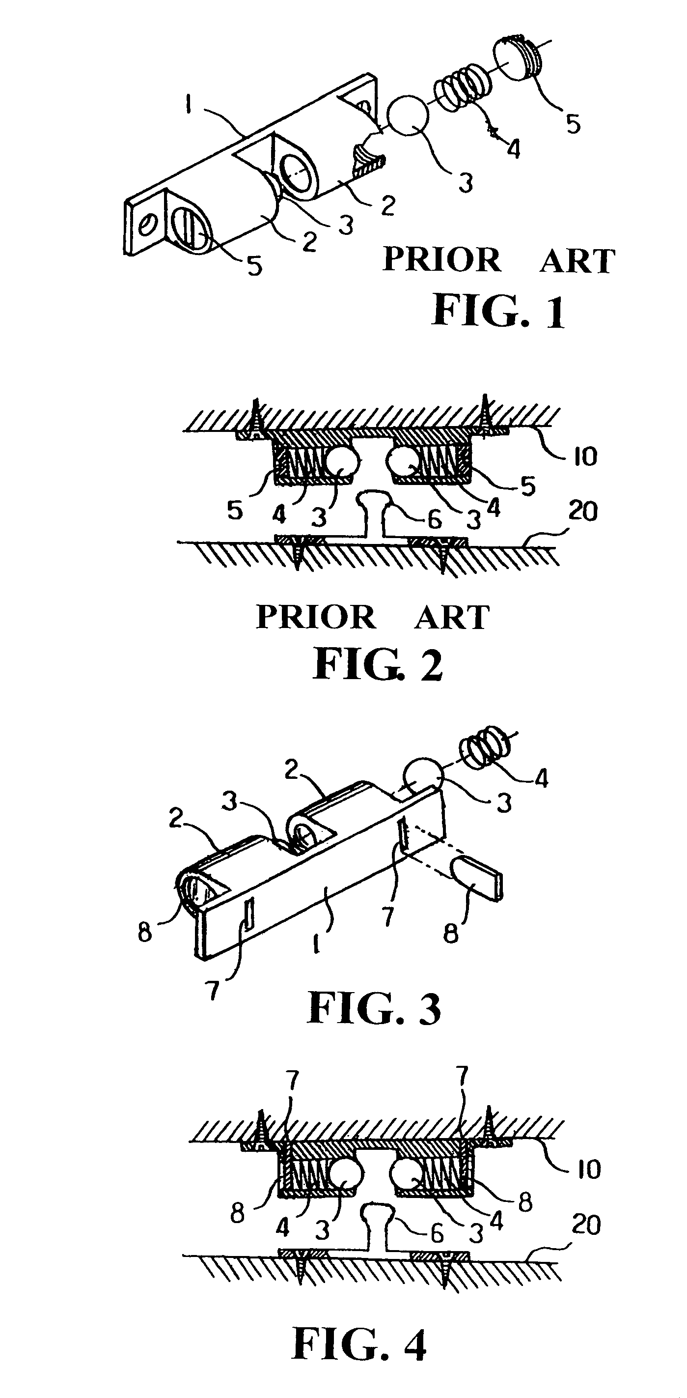
[0006]To achieve the above and other objects, the door catch according to the present invention includes a back plate having two laterally symmetric sleeves formed on a front face thereof. A slot is provided on the back plate behind each of the sleeves at a predetermined position to communicate with an inner space of the sleeve, and an insert plate is inserted from a back face of the back plate into the sleeve via the slot to confine a steel ball and a spring in the sleeve, such that the springs not only normally push the steel balls forward to partially project from front open ends of the sleeves for tightly clamping a corresponding stop post between the balls, but also tightly push against the insert plates to hold the latter in place. The insert plates are held down in place in the sleeves by a wall when the back plate is mounted on the wall with fastening elements. Therefore, the door catch of the present invention is easy to assemble and mount without the risk of loosened and / or separated insert plates.
[0007]Moreover, the whole door catch of the present invention can be made of a non-metal material to reduce the manufacturing cost thereof.

Problems solved by technology

Moreover, the conventional door catch with the above structure must be made of a metal material, and therefore requires a relatively high manufacturing cost.

Method used


Image

  • Door catch
  • Door catch

Examples


Embodiment Construction

[0015]The following descriptions are of exemplary embodiments only, and are not intended to limit the scope, applicability or configuration of the invention in any way. Rather, the following description provides a convenient illustration for implementing exemplary embodiments of the invention. Various changes to the described embodiments may be made in the function and arrangement of the elements described without departing from the scope of the invention as set forth in the appended claims.

[0016]Please refer to FIGS. 3 and 4, which are exploded perspective view and assembled top sectional view, respectively, of a door catch according to the present invention. As shown, the door catch of the present invention includes a back plate 1 having two laterally symmetric sleeves 2 formed on a front face thereof. The door catch of the present invention is characterized in that a slot 7 is provided on the back plate 1 behind each of the sleeves 2 at a predetermined position to communicate wit...


PUM


Abstract

A door catch includes a back plate having two laterally symmetric sleeves formed on a front face thereof. A slot is provided on the back plate behind each of the sleeves at a predetermined position to communicate with an inner space of the sleeve, and an insert plate is inserted from a back face of the back plate into the sleeve via the slot to confine a steel ball and a spring in the sleeve, such that the springs not only normally push the steel balls forward to partially project from front open ends of the sleeves for tightly clamping a corresponding stop post between the balls, but also tightly push against the insert plates to hold the latter in place. The insert plates are held down in place in the sleeves by a wall when the back plate is mounted on the wall with fastening elements.

Description

BACKGROUND OF THE INVENTION[0001](a) Technical Field of the Invention[0002]The present invention relates to a door catch, and more particularly to a door catch that includes two insert plates to enable easier assembling and mounting and reduced manufacturing cost thereof.[0003](b) Description of the Prior Art[0004]In a conventional door catch as shown in FIGS. 1 and 2, there is included a back plate 1 having two laterally symmetric sleeves 2 formed on a front face thereof. A steel ball 3 and a spring 4 are mounted in each of the two sleeves 2, and a screw 5 is screwed to a rear end of the sleeve 2 to confine the ball 3 and the spring 4 in the sleeve 2, so that the ball 3 is normally pushed by the spring 4 to partially project from a front open end of the sleeve 2. To use the door catch, first fixedly mount the back plate 1 on a wall 10 with fastening elements to correspond to a stop post 6 fixedly mounted on a back of a movable door leaf 20, so that the stop post 6 is clamped by and...

Claims


Application Information

Patent Timeline
Patent Type & Authority Patents(United States)
IPC IPC(8): E05C19/00
CPCE05C19/04Y10S292/15Y10T16/625Y10T16/615Y10T16/61Y10T292/14Y10T292/0808
Inventor HSU, MING-PIAO
Owner HSU MING PIAO
Why Eureka
Try Eureka