
Air cleaning apparatus

a technology of air cleaning and air filter, which is applied in the direction of auxillary pretreatment, heating types, separation processes, etc., can solve the problems of difficult cleaning of blowing fan and motor, difficult to clean filters, and primarily the removal of the cover of the cabinet, etc., and achieves the effect of easy installation or removal

Inactive Publication Date: 2006-09-26
SAMSUNG ELECTRONICS CO LTD
View PDF20 Cites 58 Cited by
  • Summary
  • Abstract
  • Description
  • Claims
  • Application Information

AI Technical Summary

Benefits of technology

[0010]Accordingly, it is an aspect of the present invention to provide an air cleaning apparatus, which is designed such that a filtering unit and a blowing unit are easily installed in or removed from a cabinet of the air cleaning apparatus, thus making it easy to clean the air cleaning apparatus and to replace filters with new filters.
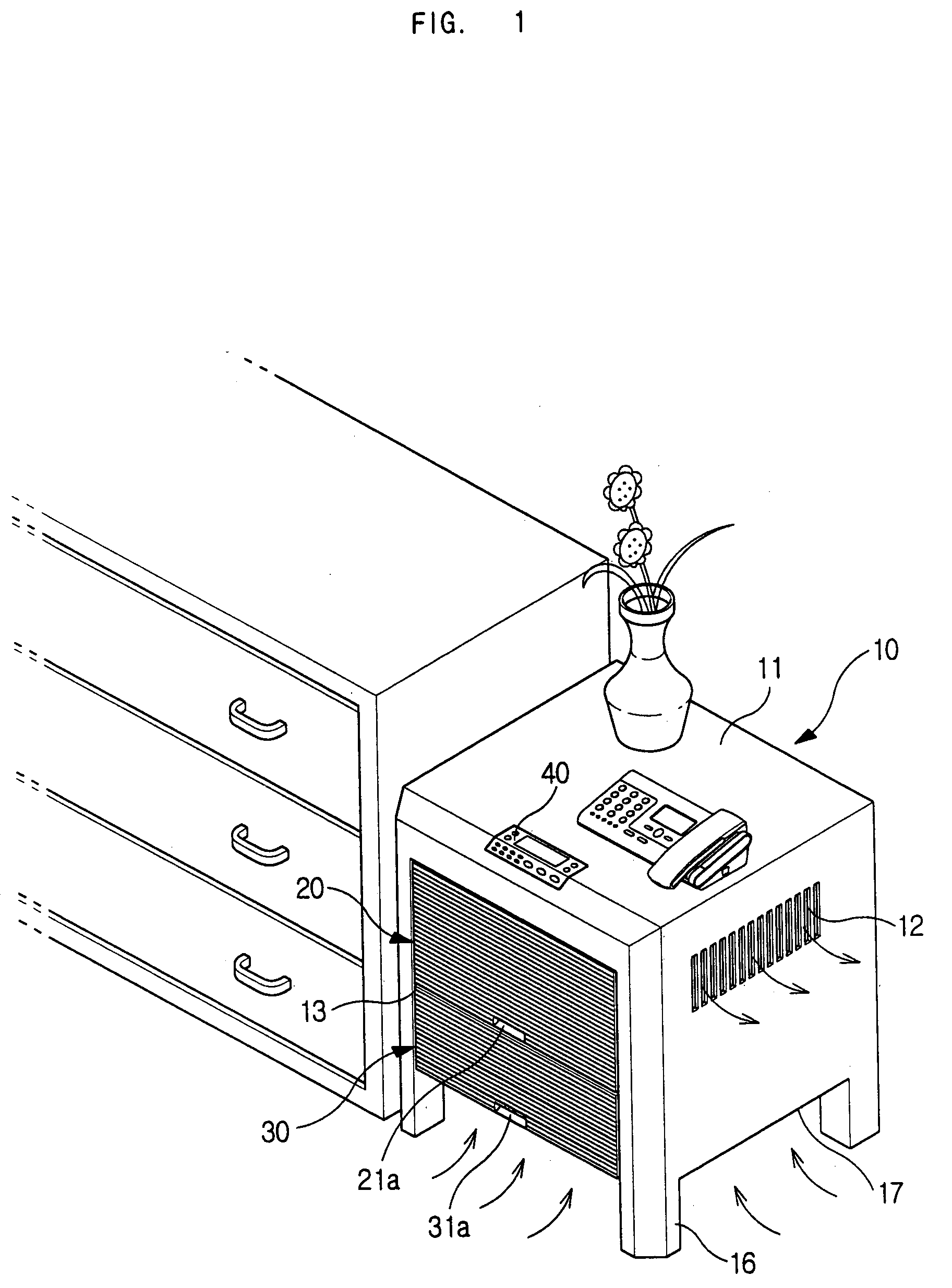
[0025]According to an aspect of the invention, a bottom of the filter casing is spaced apart from a bottom of the cabinet, allowing air to easily flow into the filter casing.

Problems solved by technology

However, the conventional air cleaning apparatus has a problem that a cover of the cabinet must be primarily removed to remove the filtering unit from the air cleaning apparatus.
The filters are also complicated to clean or replace.
The conventional air cleaning apparatus has another problem in that a blowing fan and a motor are installed in the cabinet.
Thus, it is difficult to clean the blowing fan and the motor.
However, the large-capacity air cleaning apparatus has a problem in that it performs limited functions, so its utility is poor, and it occupies a large space.

Method used


Image

  • Air cleaning apparatus
  • Air cleaning apparatus
  • Air cleaning apparatus

Examples


Embodiment Construction

[0035]Reference will now be made in detail to the present preferred embodiments of the present invention, examples of which are illustrated in the accompanying drawings, wherein like reference numerals refer to like elements throughout.

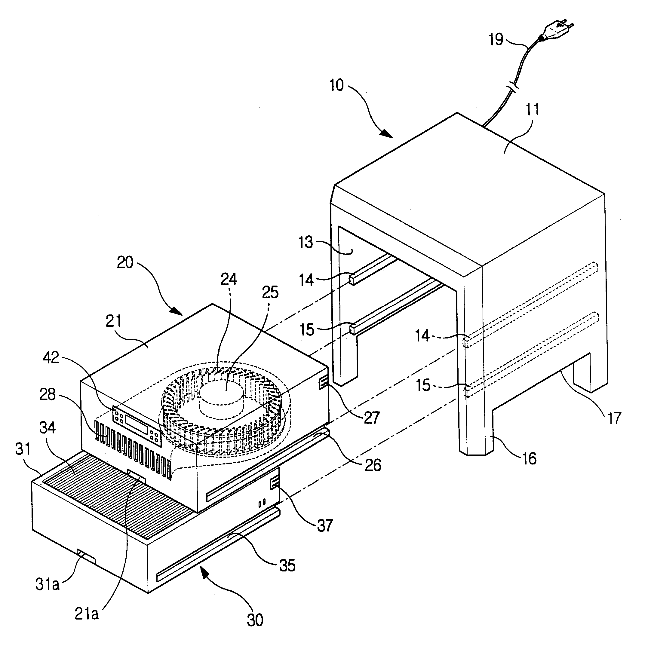
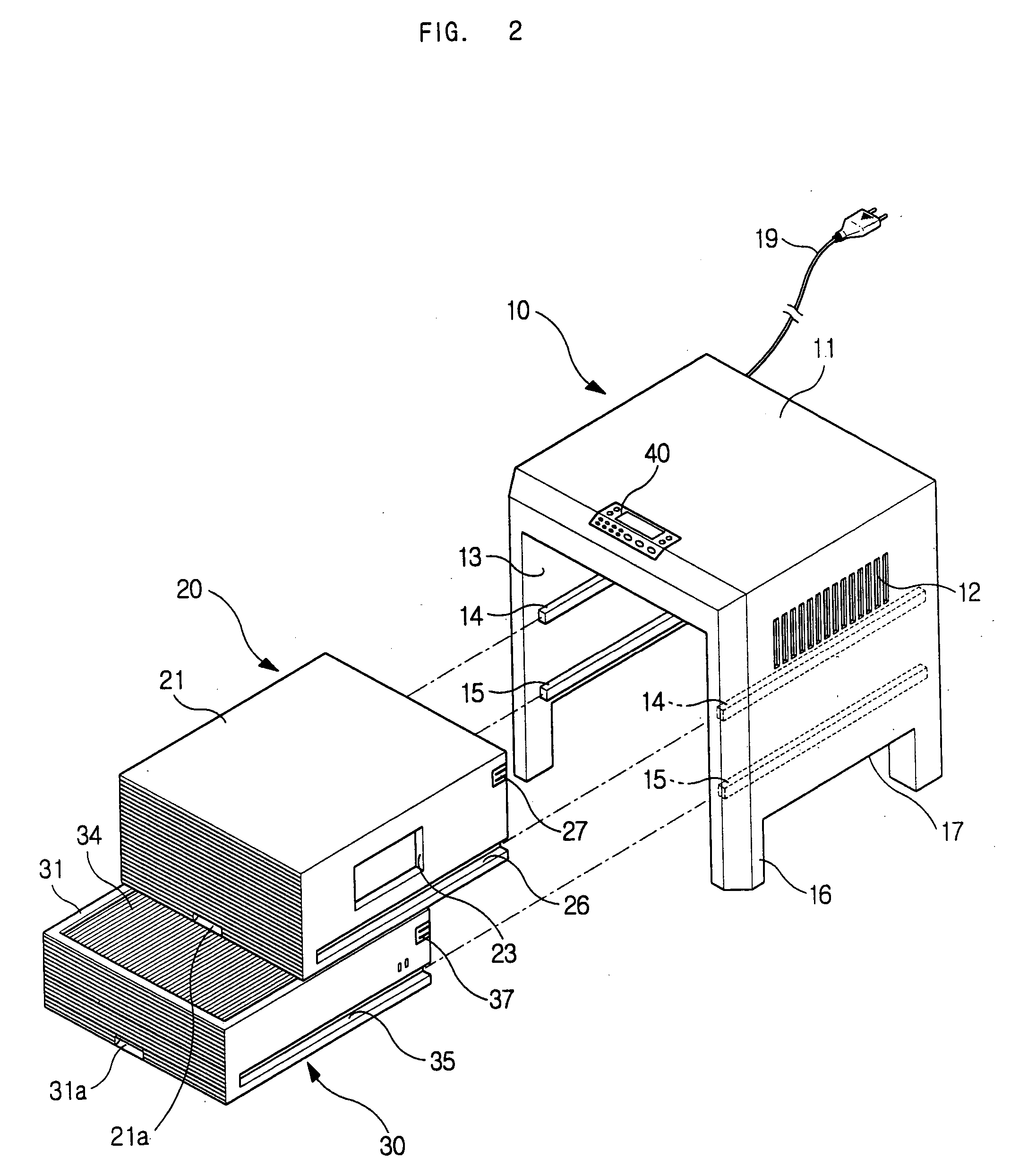
[0036]As illustrated in FIGS. 1 and 2, an air cleaning apparatus according to an embodiment of the present invention includes a cabinet 10. The cabinet 10 is provided with a flat top panel 11 of a predetermined area so that items, such as a telephone and a vase, are put on the top panel 11. The cabinet 10 has a rectangular box shape which is opened at a side and a bottom thereof. The cabinet is provided on at least one side wall thereof with an air outlet port 12.

[0037]A blowing unit 20 is installed in the cabinet 10 at a position to correspond to the air outlet port 12 to circulate room air. A filtering unit 30 is installed under the blowing unit 20 to remove impurities from the air which is circulated by the blowing unit 20. In this case, the blowin...


PUM

PropertyMeasurementUnit
areaaaaaaaaaaa
poweraaaaaaaaaa
timeaaaaaaaaaa

Abstract

An air cleaning apparatus includes a blowing unit and a filtering unit which are easily removed from and installed in a cabinet, allowing the air cleaning apparatus to be easily cleaned. The cabinet included in the air cleaning apparatus may be used as a table. The cabinet is provided with a top panel of a predetermined area, is opened at a bottom thereof, and is provided on at least one side wall thereof with an air outlet port. A fan casing is installed in the cabinet to be drawn out from the cabinet in a horizontal direction. A blowing fan is installed in the fan casing to move air to the air outlet port. A filter casing is installed under the fan casing to be drawn out from the cabinet in the horizontal direction, and at least one filter is installed in the filter casing.

Description

CROSS-REFERENCE TO RELATED APPLICATIONS[0001]This application claims the benefit of Korean Application No. 2002-82705, filed Dec. 23, 2002, in the Korean Intellectual Property Office, the disclosure of which is incorporated herein by reference.BACKGROUND OF THE INVENTION[0002]1. Field of the Invention[0003]The present invention relates, in general, to air cleaning apparatuses and, more particularly, to an air cleaning apparatus, which allows a blowing unit and a filtering unit to be easily cleaned, and which may also be used as a table.[0004]2. Description of the Related Art[0005]As is well known to those skilled in the art, an air cleaning apparatus is an appliance which removes dust or bacteria from air to clean the air. The air cleaning apparatus is provided with a blowing unit and a filtering unit. The blowing unit functions to suck room air and forcibly circulate the air. The filtering unit functions to remove the dust or bacteria from the air which is circulated by the blowing...

Claims


Application Information

Patent Timeline
Patent Type & Authority Patents(United States)
IPC IPC(8): B01D46/00B01D46/10B01D46/12B01D46/42F24F8/108F24F13/28
CPCB01D46/0006B01D46/0023B01D46/0032B01D46/10F24F3/1603F24F13/28B01D2273/30F24F2221/10F24F2003/1614F24F2003/1635B01D2279/50Y02A50/20F24F8/194F24F8/108B01D46/62B01D46/00
Inventor CHANG, JUN EUICHAE, IN APARK, JIN SOON
Owner SAMSUNG ELECTRONICS CO LTD
Learn More