Microscope apparatus

Inactive Publication Date: 2006-09-26
OLYMPUS CORP
View PDF15 Cites 2 Cited by
  • Summary
  • Abstract
  • Description
  • Claims
  • Application Information

AI Technical Summary

Benefits of technology

[0009]It is an object of the present invention to solv

Problems solved by technology

However, if the sample is thin and, particularly, if a lot of such samples are present in a culture medium, because there is no visible contrast between the samples and the background, it becomes difficult for an observer to identify individual samples.

Method used


Image

  • Microscope apparatus
  • Microscope apparatus
  • Microscope apparatus

Examples


Embodiment Construction

[0020]Exemplary embodiments of a microscope apparatus according to the present invention are explained below with reference to the accompanying drawings.

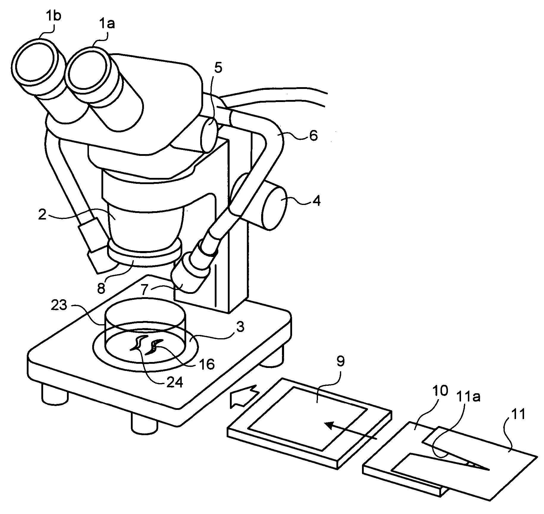
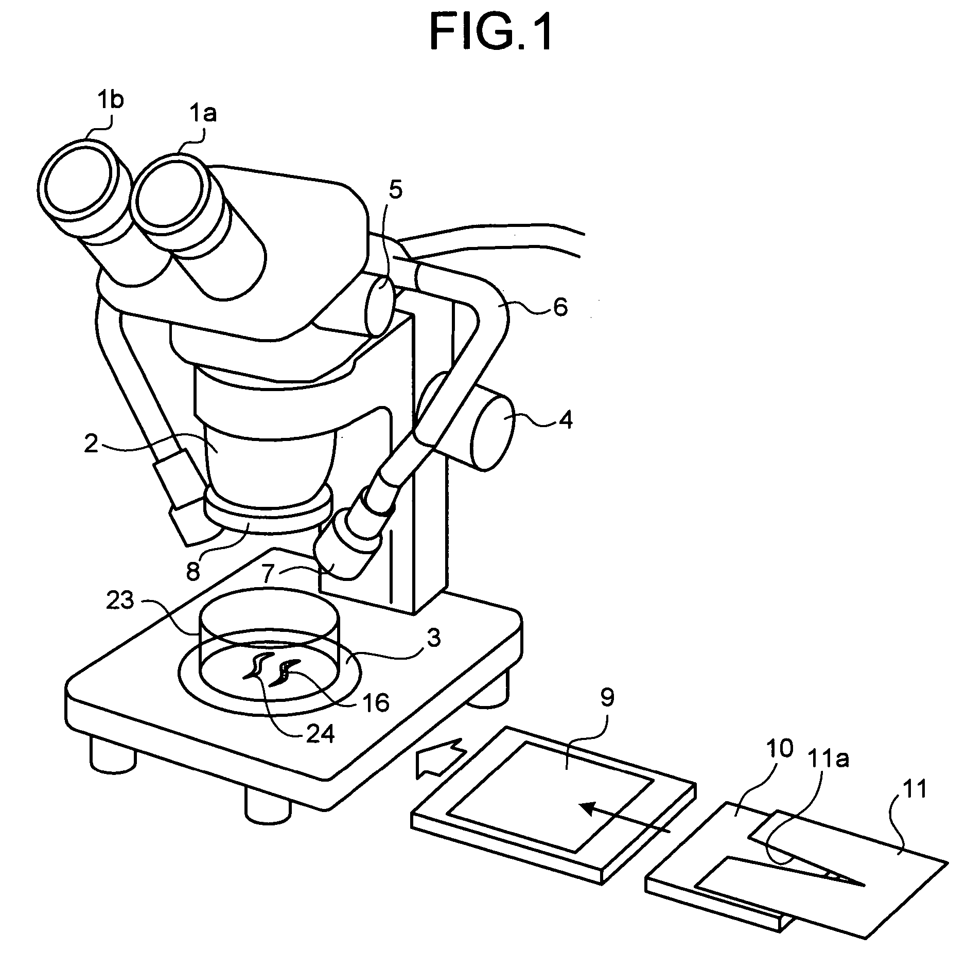
[0021]FIG. 1 is a perspective of a microscope apparatus according to an embodiment of the present invention. The microscope apparatus is a fluorescent stereomicroscope and has an optical system and a fluorescent optical system. The optical system includes an area-light source 9, a neutral-density filter 10, a wedge diaphragm 11, an absorption filter 8, a microscope body 2, a right eye piece 1a, a left eye piece 1b. The fluorescent optical system includes a light guide 6, an excitation filter 7, and the absorption filter 8.

[0022]Thin samples 16 and 24 are placed in a Petri dish 23 and the Petri dish 23 is placed on a sample stage 3. The area-light source 9 emits a light that is uniform over surface and the light is attenuated at the neutral-density filter 10. The light is then adjusted to a ratio of amount of light corresponding to f...


PUM


Abstract

An area-light source outputs uniform area light on a sample. A wedge diaphragm is placed between the area-light source and the sample. The wedge diaphragm has a notch. The wedge diaphragm is moved in a direction perpendicular to the optical axis of the area light so as to adjust an amount of the area light passing through the sample.

Description

BACKGROUND OF THE INVENTION[0001]1) Field of the Invention[0002]The present invention relates to a microscope apparatus and, more particularly, relates to a fluorescent stereomicroscope.[0003]2) Description of the Related Art[0004]Stereomicroscopes are widely used in the field of biochemistry; because, the stereomicroscopes enable stereoscopic observation of samples of various sizes and even living specimens.[0005]However, if the sample is thin and, particularly, if a lot of such samples are present in a culture medium, because there is no visible contrast between the samples and the background, it becomes difficult for an observer to identify individual samples.[0006]One approach is to provide a shade between an area-light source, which emits uniform area light on the sample, and the sample and continuously adjust the light of the area-light source that is incident directly on an object lens (Japanese Patent Application Laid-open Publication No. H11-133308).[0007]Other approach is ...

Claims


Application Information

Patent Timeline
IPC IPC(8): G02B21/06G02B21/00G02B26/02G02B9/08G02B21/16G02B21/22
CPCG02B21/16G02B26/02G02B21/22
Inventor KANEDA, TORU
Owner OLYMPUS CORP
Why Eureka
Try Eureka