Drainage system for sports fields

a drainage system and sports field technology, applied in the field of undersurface drainage systems, can solve the problems of liners not being able to independently correct the problems, prone to rupture and other failure, and not easy to retain sand on sloped sides

Inactive Publication Date: 2006-10-03
WILKERSON DENNIS JAMES
View PDF36 Cites 25 Cited by
  • Summary
  • Abstract
  • Description
  • Claims
  • Application Information

AI Technical Summary

Benefits of technology

[0011]In another embodiment of the invention, a pipe or piping system is connected to the receptacle to collect water and direct water toward the receptacle. The pipe or piping system may or may not be perforated and can be divided into a water collection system having two or more branches for covering a larger surface, such as the area of a bunker or the sides of a playing field.

Problems solved by technology

Fabric liners do not easily retain the sand on the sloped sides and are subject to rupture and other failure.
Such liners do not independently correct the problems associated with accumulation of rainwater in the bunkers.
Such systems eventually fail in wet climates because the clay linings are susceptible to erosion.
Over time the accumulated intrusion clogs the pipe which requires new construction of the entire bunker.
Such construction is not only expensive to accomplish but also disrupts the utility of the golf course during construction.
Standing water in low areas contributes to damage of living plants in landscaped areas and leaves residual flotsam, debris and watermarks which destroy and compromise the surface design and appearance.
Bohnhoff further describes conventional perforated pipe networks and the problems associated with poor drainage.
In bunkers having perforated pipe drains, clay fines inevitably pack off the pipe at the lowest point in the bunker.
This occurrence causes excess water to pond at this position within the bunker, further accelerating deterioration of the bunker drainage system.

Method used


Image

  • Drainage system for sports fields
  • Drainage system for sports fields
  • Drainage system for sports fields

Examples


Embodiment Construction

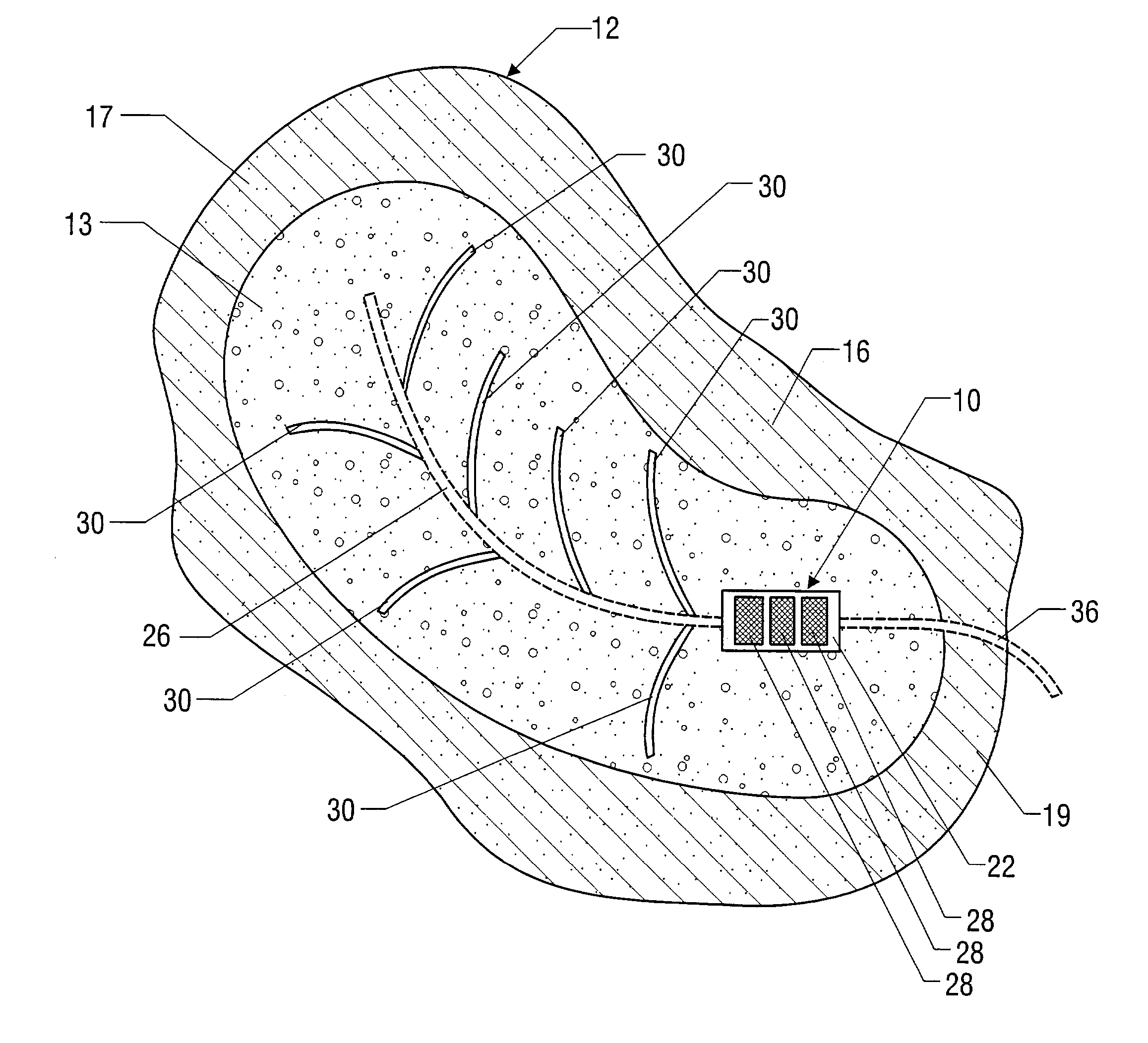
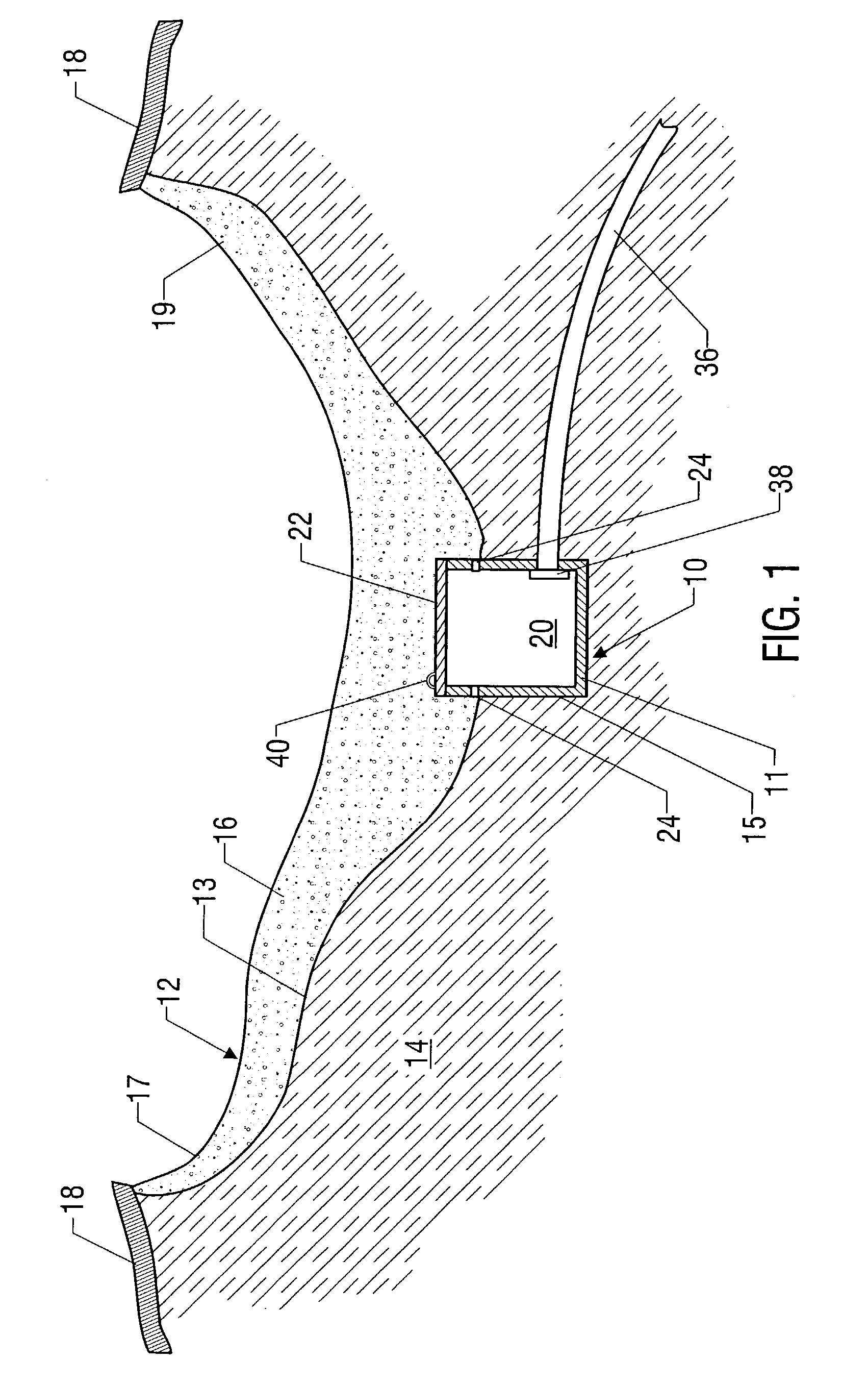
[0021]The invention provides a method and apparatus for draining water from a bunker or other sports field having a surface covered with sand or other playable or usable sports surface. The invention is also applicable to drainage of landscaped areas. FIG. 1 illustrates receptacle or box 10 positioned within bunker 12 which comprises soil 14 and sand 16. Bunker 12 is irregularly shaped and is sloped toward one or more ends so that excess water collects toward the low end of bunker 12. Soil 14 can comprise existing soil, imported material such as clay, stabilized soil material, or other conventional bunker or sports base material. Bunker 12 has sloped sides 17 and 19 which terminate at the ground elevation of turf 18 so that bunker 12 forms a golf playing hazard below the ground elevation of turf 18.

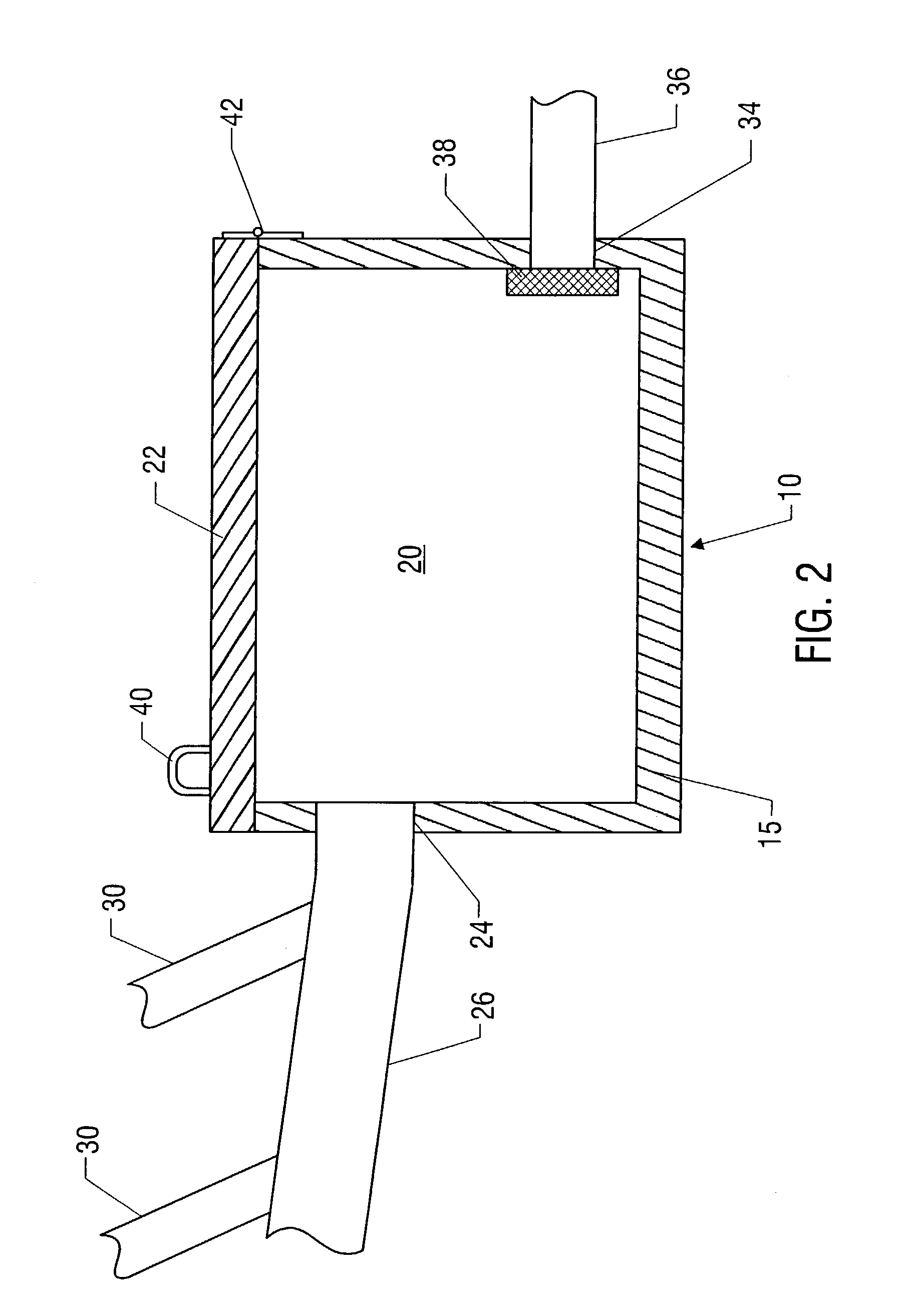
[0022]Receptacle or box 10 comprises a substantially hollow bucket, basin, container, or vessel 15 having interior space 20 and is formed with a material resistant to degradation such as ...


PUM


Abstract

An improved system for draining bunkers on golf courses and other sports playing areas, and for draining landscaped areas. A receptacle is positioned below the surface for receiving drain water and for discharging the water through an outlet. A perforated pipe water collection system can be attached to the receptacle to direct water to the receptacle interior space. A receptacle cover is removable to permit access to the receptacle interior space. The cover is sufficiently strong to support the overlying weight of people and equipment, and can have apertures for permitting water entry while resisting entry of sand and other solids into the interior space of the receptacle.

Description

CLAIM TO PRIORITY[0001]This application is a continuation-in-part of application Ser. No. 10 / 000,740 filed Oct. 31, 2001.BACKGROUND OF THE INVENTION[0002]The invention relates to under-surface drain systems and particularly systems for bunkers in golf courses, drainage areas in sports fields, such as the areas along the sides of tennis courts, and football, baseball, and soccer fields; and landscape areas where under-surface drainage systems are required or preferred for consistent surface appearance and integrity.[0003]A golf course imposes unique design requirements on turf systems and sand bunkers on the course. Bunkers are deliberately positioned to create artificial hazards for errant golf balls The bunkers are typically constructed as depressions having a clay base with sloped sidewalls rising upward to surrounding turf. The bunkers have specific peripheral configurations, depth, and sloped sides. Sand overlays the clay base or other base material to provide the playing surfac...

Claims


Application Information

Patent Timeline
Patent Type & Authority Patents(United States)
IPC IPC(8): A01G25/06E02B11/00E01C13/02
CPCE01C13/02E02B11/00
Inventor WILKERSON, DENNIS JAMES
Owner WILKERSON DENNIS JAMES
Why Eureka
Try Eureka