Mesh connected electrical rotating machine with span changing

a technology of electrical rotating machines and span changing, which is applied in the direction of motor/generator/converter stoppers, electronic commutators, dynamo-electric converter control, etc., can solve the problems of device failure, inverter cost considerably greater than the cost of motor supply, and severe limit in the overload capability of inverter electronics, etc., to achieve high torque overload

Inactive Publication Date: 2006-10-03
BOREALIS TECH LTD
View PDF14 Cites 75 Cited by
  • Summary
  • Abstract
  • Description
  • Claims
  • Application Information

AI Technical Summary

Benefits of technology

[0019]A technical advantage of the present invention is that high torque overload may be provided at low speeds whilst sufficient voltage is also provided for high-speed applications.
[0020]A further technical advantage of the present invention is that the spanning value L may be altered in a particularly simple switching arrangement to obtain a change in operational Volts / Hz ratio.
[0021]A further technical advantage of the present invention is that varying the phase angle difference across each motor phase by changing the harmonic applied by the inverter to the mesh connection, provides a change in Volts / Hz ratio through a logical change of the output synthesized by the inverter. This means that the motor may have a fixed electrical connection to the inverter. A yet further technical advantage is that the change in harmonic content may be obtained in a smooth fashion, successively passing through various admixtures of harmonic components.
[0022]A further technical advantage of the present invention is that by changing the spanning value L, the same machine pole count is maintained.BRIEF DESCRIPTION OF THE SEVERAL VIEWS OF THE DRAWING
[0023]For a more complete understanding of the present invention and the technical advantages thereof, reference is made to the following description taken with the accompanying drawings, in which:
[0024]FIG. 1 is a diagrammatic representation of a motor stator and windings

Problems solved by technology

In many cases, the cost of the inverter is considerably greater than the cost of the motor being supplied.
Whereas the alternating current machine itself may have substantial overload capability, and may carry currents of the order of five to ten times full rated current for periods measured in minutes, the overload capability of the inverter electronics is severely limited.
Exceeding the voltage or current ratings of the inverter electronics will swiftly cause device failure.
Voltage overload is normally not specified, and will cause near instantaneous destruction of semiconductor elements.
With any reasonably sized inverter, substantial motor overload capabilities remain untapped.
Electrical rotating machinery presents impedance that changes with mechanical load and rotational velocity.
In many traction application, there is limited available electrical power.
Thus requirements for high overload capability can only be met at low speed, where high torque is required for starting, but reduced speed means that mechanical power output is still low.
This increase in overload capability comes at a substantial cost.

Method used


Image

  • Mesh connected electrical rotating machine with span changing
  • Mesh connected electrical rotating machine with span changing
  • Mesh connected electrical rotating machine with span changing

Examples


examples

[0069]Specific examples are offered to enhance the disclosure and understanding of the present invention. These examples should in no way be considered limiting. These examples may be considered ‘best mode’ descriptions, in so far as the optimal motor for any given application will vary considerable with the mechanical requirements of the application. These descriptions will focus upon the differences between the present invention and the prior art, and as such will not focus upon details which are both well known in the art, and unchanged by the present invention, for example bearings or motor housing materials.

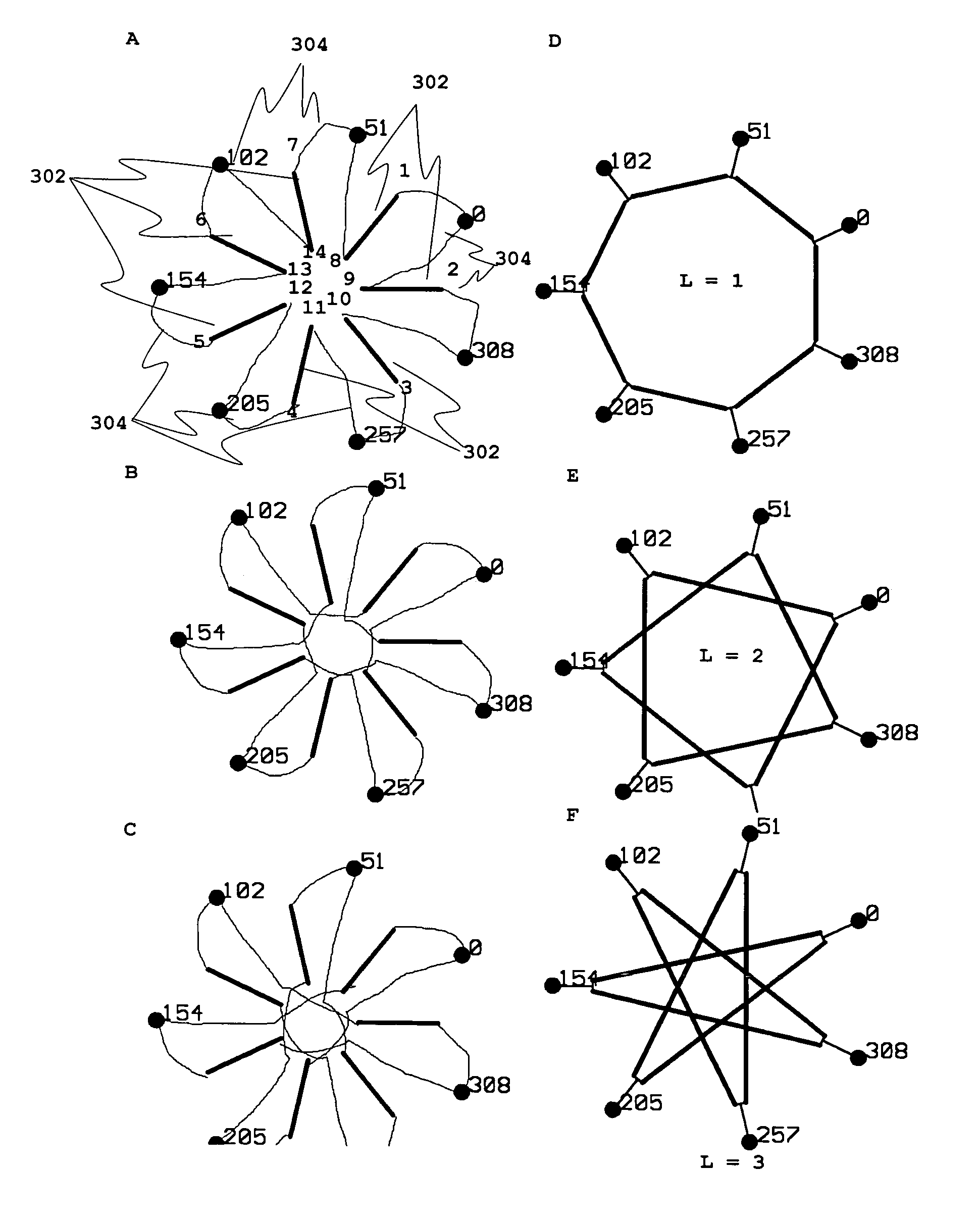
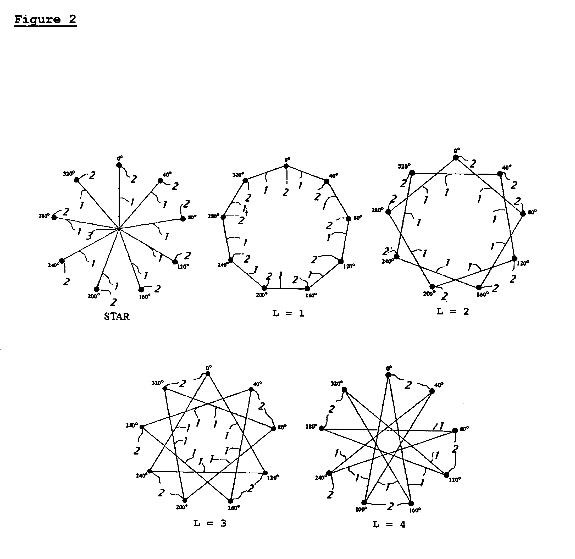
[0070]To better illustrate the scope of the present invention, Tables 2 and 7 and FIGS. 7 to 12 indicate the possible mesh connections and voltages for 5 and 15 phase devices. In the Tables, the value for V is the voltage across the winding when 1.0 volt is applied by a star connected source.

[0071]

TABLE 25 Phase Mesh Connections.L = 1;L = 2;V = 1.176V = 1.902402406 1st406 2n...


PUM


Abstract

An electrical rotating apparatus is provided that has variable impedance. This is achieved by connecting one of the polyphase components of the apparatus in a mesh connection. The spanning value, L, of such a mesh connection may be varied by changing the harmonic content supplied by an inverter component. Also provided is a method for connecting an inverter to a motor, wherein a switching arrangement permits the simple alteration between various mesh connections of different span value, changing thereby the Volts / Hertz ratio of the motor.

Description

CROSS-REFERENCE TO RELATED APPLICATIONS[0001]The present invention is a Divisional of U.S. patent application Ser. No. 10 / 132,936 filed Apr. 26, 2002 now U.S. Pat. No. 6,838,791, and which claims the benefit of U.S. Provisional App. No. 60 / 286,862 filed Apr. 26, 2001. U.S. patent application Ser. No. 10 / 132,936 is a Continuation-in-part of U.S. patent application Ser. No. 09 / 713,654, filed Nov. 15, 2000 now U.S. Pat. No. 6,657,334.BACKGROUND OF THE INVENTION[0002]The present invention relates to motors and their inverter drives. In particular it related to methods and apparatus for connecting polyphase devices.[0003]An alternating current motor is commonly driven by an inverter. An inverter is a device capable of supplying alternating current of variable voltage and variable frequency to the alternating current motor, allowing for control of machine synchronous speed and thus of machine speed. The inverter may also be used with alternating current generators, and can cause an altern...

Claims


Application Information

Patent Timeline
Patent Type & Authority Patents(United States)
IPC IPC(8): H02K37/24H02K3/28H02K5/22H02K17/12H02P25/18H02P27/00H02P29/00
CPCH02K3/28H02K11/0073H02K17/12H02P25/18H02P25/22H02P27/00H02P29/0038H02K5/225H02K11/33H02P29/50
Inventor EDELSON, JONATHAN SIDNEY
Owner BOREALIS TECH LTD
Why Eureka
Try Eureka