
System and method for continuous online safety and reliability monitoring

a technology of online safety and reliability monitoring and monitoring system, applied in the direction of testing/monitoring control system, process and machine control, etc., can solve the problems of substantial energy and monetary interests, system and process complexity, and the potential to inflict serious harm on persons or properties

Active Publication Date: 2006-10-03
SCHNEIDER ELECTRIC SYST USA INC
View PDF3 Cites 21 Cited by
  • Summary
  • Abstract
  • Description
  • Claims
  • Application Information

AI Technical Summary

Benefits of technology

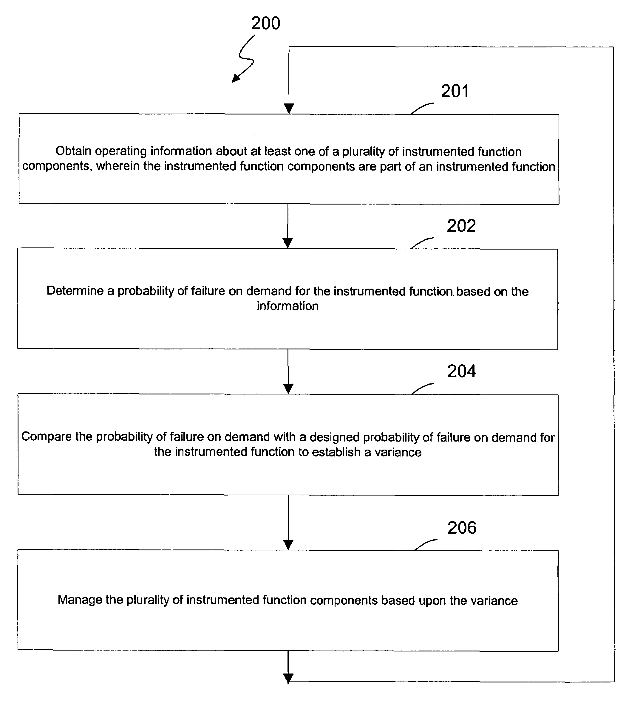
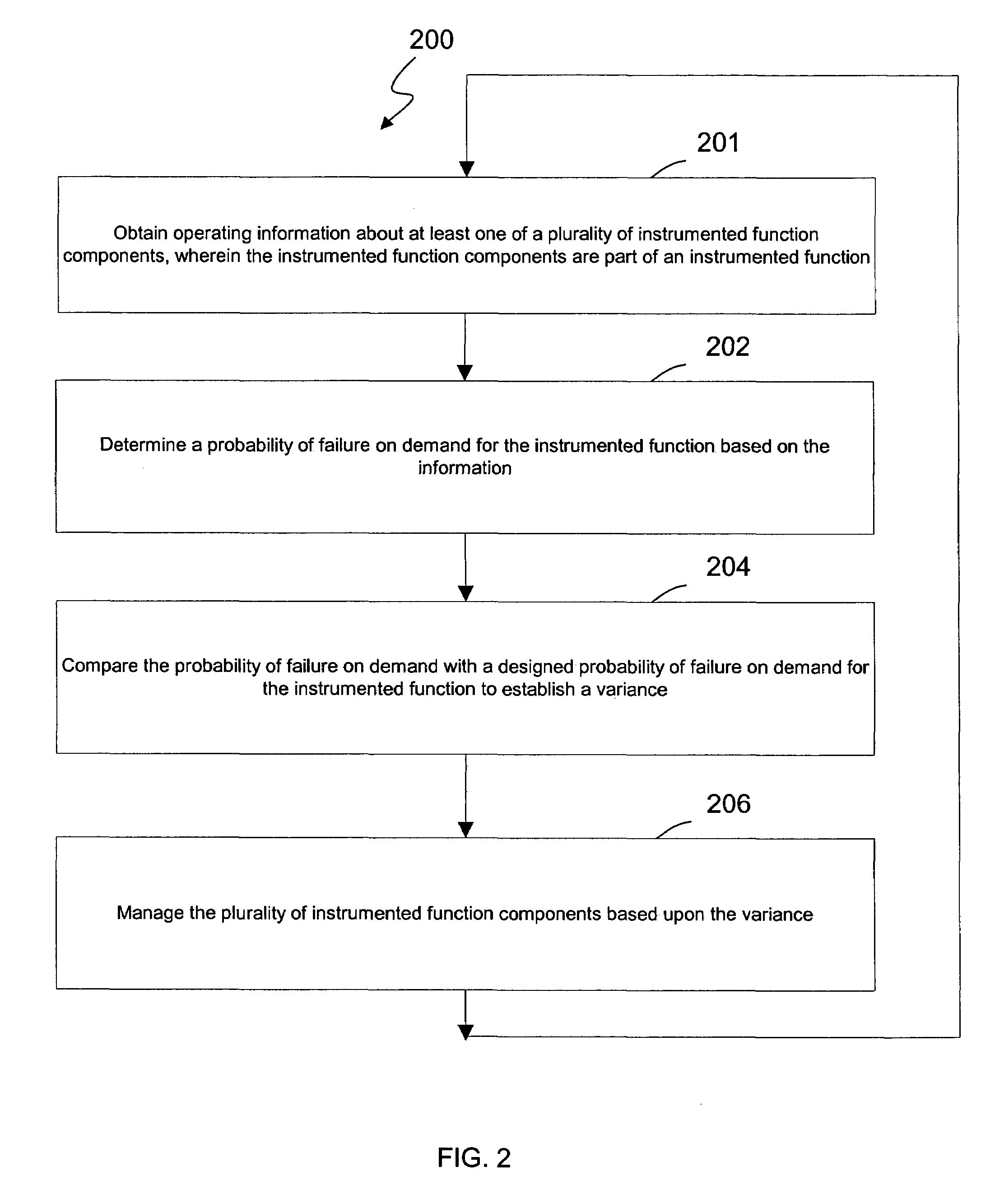
The invention is a method, system, and processor-readable medium for managing a safety instrumented function that includes multiple components. The method involves obtaining operating information about the components, determining the probability of failure on demand for the function, comparing it with a designed probability of failure on demand, and managing the components based on the variance. The system includes an asset management application and an online safety integrity level application, which communicates with the asset management application to receive and calculate the probability of failure on demand. The processor-readable medium includes instructions for obtaining operating information, determining the probability of failure on demand, and generating safety availability information. The technical effects of the invention include improved safety management and reliability of the safety instrumented function.

Problems solved by technology

Modern industrial systems and processes tend to be technically complex, involve substantial energies and monetary interests, and have the potential to inflict serious harm to persons or property during an accident.
Unfortunately, after a SIS is operational, a plant engineer is unable to determine what the average PFD or SIL levels are for a SIF once actual testing varies from the regimented test schedule.
Furthermore, the actual PFD and SIL levels will vary depending upon actual environment conditions, and as a consequence, a plant engineer will face further uncertainty as to what the actual PFD and SIL level is for the SIF.

Method used


Image

  • System and method for continuous online safety and reliability monitoring
  • System and method for continuous online safety and reliability monitoring
  • System and method for continuous online safety and reliability monitoring

Examples


Embodiment Construction

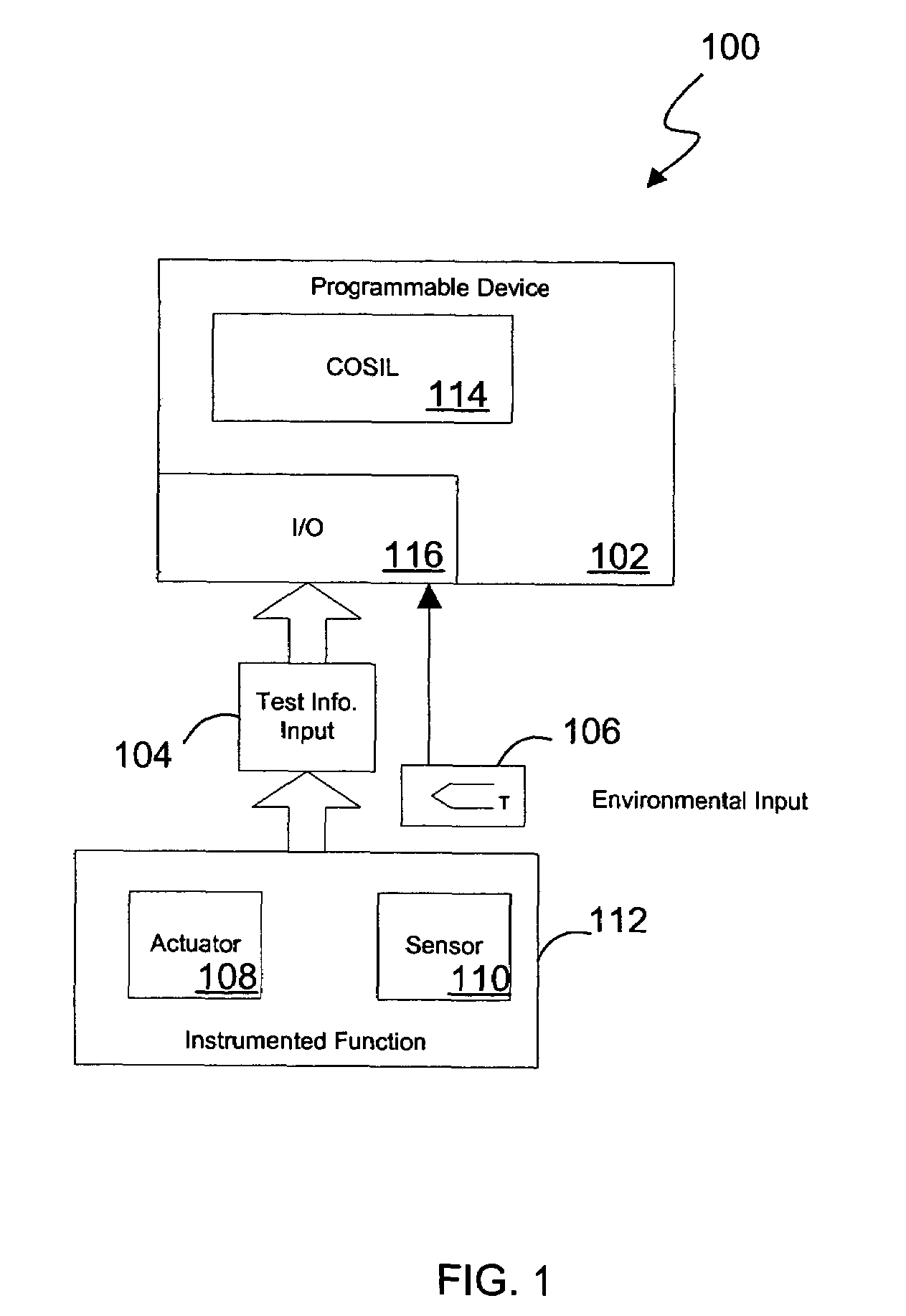
[0030]In one aspect, the present invention is directed to a safety and reliability monitoring system, also referred to herein as a COSIL™ system, which provides historical, real time and predictive probability failures for an online instrumented system, e.g., a safety instrumented system (SIS), based on events which occur during operation and maintenance of the instrumented system.

[0031]Unlike current approaches for evaluating safety and reliability, which are generally based upon static offline calculations using assumed average conditions over the life cycle of the instrumented system, the present invention according to several embodiments is capable of providing dynamic, online calculations of average probability of failure on demand, instantaneous probability of failure on demand, and safety integrity level (SIL) using actual events (e.g. time of test) in an industrial plant. In some embodiments, the present invention also provides reliability information (e.g., mean time to fai...


PUM


Abstract

A system and method for continuous online safety and reliability monitoring is disclosed. The method includes the steps of obtaining operating information about at least one of a plurality of instrumented function components, which are part of an instrumented function, and determining a probability of failure on demand for the instrumented function based on the operating information. In variations, operating information includes status information, which may be received from and / or provided to an asset management application. In some variations, instantaneous probability of failure on demand, online mean time to failure (MTTF), and online safety integrity level (SIL) are also calculated for an instrumented function. In yet further variations, the system allows a user to predict probability of failure on demand values into the future based on hypothetical and / or future planned test times.

Description

CROSS REFERENCE TO RELATED APPLICATIONS[0001]This application claims priority under 35 U.S.C. § 119(e) to U.S. Provisional Patent Application Ser. No. 60 / 491,999 filed Aug. 1, 2003, entitled: SYSTEM AND METHOD FOR CONTINUOUS ONLINE SAFETY AND RELIABILITY MONITORING, which is incorporated herein by reference. This application also relates to co-pending U.S. patent application Ser. No. 10 / 684,329, filed Oct. 10, 2003, of Van Dyk, et al.; entitled SYSTEM AND METHOD FOR CONTINUOUS ONLINE SAFETY AND RELIABILITY MONITORING.BACKGROUND OF THE INVENTION[0002]1. Field of the Invention[0003]The present invention relates generally to control and monitoring systems, and more specifically to industrial safety and reliability control and monitoring systems.[0004]2. Discussion of the Related Art[0005]Modern industrial systems and processes tend to be technically complex, involve substantial energies and monetary interests, and have the potential to inflict serious harm to persons or property during...

Claims


Application Information

Patent Timeline
Patent Type & Authority Patents(United States)
IPC IPC(8): G06F15/00G05B23/02
CPCG05B9/02G05B23/0283
Inventor VAN DYK, PAUL J.ADAMSKI, ROBERT S.POWERS, LESLIE V.MCCREA-STEELE, ROBINBARRON, DAVID
Owner SCHNEIDER ELECTRIC SYST USA INC
Learn More